
Manuscript accepted on :17-01-2020
Published online on: 30-01-2020
Plagiarism Check: Yes
Reviewed by: Thippa Reddy Gadekallu
Second Review by: Narasimha Murthy
Final Approval by: Dr Ayush Dogra
Bhumika Gupta1  , Agya Ram Verma2*and Manoj Kumar2
1Department of Computer Science Engineering G.B.Pant Institute of Engineering and Technology, India
2Department of Electronic and Communication Engineering G.B.Pant Institute of Engineering and Technology, India
Corresponding Author E-mail : arverma06ei03@gmail.com
DOI : https://dx.doi.org/ 10.13005/bpj/1855
Abstract
In this paper, we propose the design of the Quadrature Mirror Filter (QMF) two-channel linear phase bank with modified particle swarm optimization (MPSO) algorithm. Traditional other reported methods for QMF bank design, were compared to the performance of proposed scheme. Based on simulation results, it is shown that the stated method can achieve 26%, 83%, 97%, 84% as well as 67%, respectively reduction in amplitude, transfer band, impede band, alteration band, with peak reconstruction errors. In comparison, the proposed QMF bank applied for biomedical image reconstruction shows 2.2 folds reduction in mean square error with an improvement of 5 dB in peak signal-to-noise ratio as compared to recently reported Levenberga algorithm.
Keywords
Biomedical Image; MPSO; Sub-Band Coding; PSO; QMF
Download this article as:| Copy the following to cite this article: Gupta B, Verma A. R, Kumar M. A Novel Approach of QMF Bank Using Modified PSO Technique for Biomedical Image Applications. Biomed Pharmacol J 2020;13(1). |
| Copy the following to cite this URL: Gupta B, Verma A. R, Kumar M. A Novel Approach of QMF Bank Using Modified PSO Technique for Biomedical Image Applications. Biomed Pharmacol J 2020;13(1). Available from: https://bit.ly/2U6Ihe0 |
Introduction
Work on efficient design of two-channel quadrature mirror filter (QMF) banks has gained significant attention over the past two decades, because they are used in wide range of applications like speech signals [1, 2], image processing [3] and communication systems [4, 5]. In the past, particle swarm optimization (PSO) technique and its different variants were employed in order for improving performance of QMF banks [6, 7]. In these algorithms, different stables (weights) were shortlisted on hit with trial basis for a boundary filter length. Recently, several authors have proposed gradient based approach to design QMF banks to improve performance for filterbank for sub-band coding [8–14]. The design problem was developed using filter response in ideal condition and complete reconstruction in these methods. The authors in [15, 16] have used fractional derivative constraintsfor digital filter design and this was further extended for filter bank [17, 18].The authors have used other evolutionary practices like artificial bee colony (ABC) algorithm [19] and differential evolution (DE) [20] for the design of QMF bank. However, in this report, different variants of modifiedPSO (MPSO) have not been studied. Therefore, motive of this work is todesign QMF bank using different types of MPSO algorithms by adjusting ω so that the filter achieves optimum value of all fidelity parameters for different input signals. The proposed technique provides better performance overthe other algorithms reported in literature. Moreover, the proposed QMFbank with MPSO scheme is applied for efficient reconstruction of a magneticresonance imaging (MRI) brain image.
Formulation of QMF bank
Fig. 1 displays a two channel QMF block diagram in which input signal is split into two bands with one LPF (h0(z)) moreover other HPF (H1(z)) study filters. Their outputs are <ICON 1>k(n) where k = 0, 1. Which are passed to get an output (Uk(n)) through the down-sampler. Such signals are transmitted via a channel. The signals are passed through the up-sampler at the receiver end to obtain <ICON 1>k(n) moreover then added to the synthesis filter LPF furthermore HPF (Gk(z)).
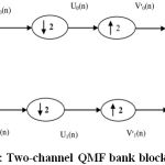 |
Figure 1: Two-channel QMF bank block diagram |
Finally, the signals are combined to obtain renovated yield (y(n)). The output via QMF system can be written as [21, 22] :
Y (z) = 0.5[H0(z)G0(z) + H1(z)G1(z)]X(z) + 0.5[H0(-z)G0(z) + H1(-z)G1(z)]X(-z) (1)
The above output can also be represented as:
Y (z) = 0.5[t(z)]X(z)+ 0.5[a(z)]X(-z) (2)
The term t(z) is referred to as distortion transfer function and the term a(z) is referred to as an aliase. Term a(z) would be zero for no alises. QMF bank’s overall frequency response reduces to [6]:
T(ejω) = 0.5 e– jω(N-1)/2[|H0(ejω) |2 – (-1)N| H0(ej(ω-π)|2] (3)
If filter order (N-1) is even then the above expression will be reduced to zero at ω = 0.5π which is not required for the original signal to be perfectly reconstruction. So, we took (N-1) as odd furthermore Eq. 3 can be written as:
t(ejω) = 0.5(e−jω(N−1)[|H0(ejω)|2 + |H0(ej(ω−π))|2]) (4)
If H0(ejω) posses perfect response in pass-band and stop-band, the error of reconstruction in transition band exists. In order to improve overall performance, one has to optimize the amplitude response in transition band. The filter bank’s overall amplitude response is provided by:
|T(ejω)| = |T(ω)| = |H0(ω)|2 + |H0(ω − π)|2 (5)
For an ideal prototype LPF, the amplitude response is written as:

Here ωp is frequency of pass-band furthermore ωs is frequency of stop-band. By replacing the h0(ω) value from Eq. 6 in Eq. 5, we obtain overall transfer function depicted:
![]()
The amplitude response of |T(ejω)| is unity at cut-off frequency ωc = π/2, for perfect reconstruction.
![]()
![]()
![]()
From above amplitude response, we derived objective function:
φ = et + αep + (1 − α)es + α.eam (11)
where et, ep, and es represent the errors in transition-band, pass-band, and stop-band furthermore eam shows the measure of amplitude ripples. These errors are formulated as:
et = [1 − 0.707h0(ω)]2|ω= 0.5π (12)
![]()
![]()
eam = max(|T(ω)|) − min(|T(ω)|) (15)
Optimization of QMF with MPSO Technique
Solution of non linear Eqs. 12 – 15, the PSO technique which begins by initialization of a random swarm of M particles with R unspecified parameters to be optimized. The algorithm stock ups moreover gradually reinstates each particle’s most fit position parameter (pbest, i = 1, 2, …, M) furthermore most suit group velocity parameter (gbest). But, if the signal period is long, the cutting-edge PSO faces troubles [14]. Therefore, by using introducing an inertia weight (w) parameter the PSO is changed. In MPSO, every particle’s velocity (v(n)) and position (p(n)) are changed by means of the noted equations:
v(n) = w ∗v(n−1)+c1∗r(0, 1)∗(gbestp(n1))+c2∗r(0, 1)∗(pbest −p(n1)) (16)
p(n) = p(n − 1) + vel(n) (17)
Here vel(n) is the nth iteration velocity vector of particle, r(0, 1) is random value vector between (0, 1), furthermore c1, c2 are the gbest and pbest acceleration coefficients. The update position is performed only if the current position p(n) performs better than the previous p(n − 1) position. The MPSO technique is used to minimize the objective function (Eq. 9) which provides the coefficients (h(n), n = 1, 2, …, m) of optimum QMF bank. In this process, the main objective is to evaluate the pbest and gbest for each particle and update their values in every iteration. The iteration ends when the fitness function ((φ1)) given below becomes less than a pre-specified tolerance value (ϵp= 0.1).
φ1 = min(K) (18)
In which K is the preliminary enter of MPSO. Exploration moreover development may be noted as primary features of MPSO. Exploration show how the technique for higher overall performance will cover more search location whereas exploitation shows accurate convergence to a particular point. Those characteristics depend upon the w parameter. Expanded cost of w gives more exploration while exploitation is higher for squat fee of w. Consequently, w is a vital parameter which must be up to date cautiously. Initially, the w is assigned a high fee that’s lowered as iteration is going in the direction of the quit [7]. The implementation steps of MPSO are as follows:
Stride 1 Position furthermore velocity is initialized for each particle.
Stride 2 Fitness value ((φ1)) is computed for each particle thru Eq. 18.
Stride 3 Find the particle with finest fitness value furthermore initialize its area in an effort to gain the squat fitness value. If lowest fitness value is appropriate then replace the placement by using assigning the particle new random cost in step with eq. 16 & 17 for area furthermore velocity.
Stride 4 Evaluate the fitness cost with pbest for each particle furthermore update if it is higher than the pbest.
Stride 5 Primarily based on its fitness cost, decide the excellent particle furthermore replace if it’s miles higher than the gbest.
Stride 6 Take a look at for concluding condition, if new release is glad otherwise it’s going to again start with stride 3.
From equations 16 and 17, it is clear that w is an essential parameter affecting the speed and function of every particle in MPSO. Depending on choice of w, the MPSO technique is classified into special classes. In steady weight inertia (CWI) MPSO, the w is stored constant among 0 to 1 for every particle and at any time immediate, the inertia weight (wt) is given via:
wt = c (19)
However, a regular value of wt won’t cause most excellent exploitation and exploration in the simulation procedure for diverse alerts. Consequently, for better performance of MPSO, an adaptability in wt is required. In case of dynamic inertia (DI) MPSO [22], the wt is up to date in every iteration as:
![]()
Here, rand(.)t is the random feature producing numbers uniformly allotted between 0 and 1. Due to the fact the brand new wt in every generation is unrelated to the previous one cost, there’s hard to pick out the random value to gain better exploitation and exploration. To triumph over this, a linear decay inertia (LDI) MPSO is used in which wt is up to date in each iteration in a linear among most and minimum values. The generation procedure begins with maximum fee of wt and decremented because the iteration progresses. For(LDI) MPSO, the wt after every iteration is written as:

Where in wmin moreover wmax represents least furthermore most values of wt, along tmax denotes the most time of iterations. Despite the fact that, LDI MPSO offers better outcomes for exploitation [22] but exploration isn’t always optimized as consistent with requirement. For improving exploration, the non-linear inertia (NLDI MPSO) is used wherein Eq 21 is modified by using introducing non-linearity [18] as:
![]()
here n is the index of non-linear modulation.
The performance parameters of clear out are evaluated the use of following equations:
PRE = max[20log10[|H0(ejω)|2 + |H0(ej(ω−π))|2]] (23)
As = −20log10[|H0(ω)|] |ω=ωs (24)
In which PRE is the peak restoration error, furthermore As denotes the forestall-band attenuation. It could be mentioned that we’ve got taken coefficients of 32 faucet filter out with ωp = 0.4π, ωc = 0.5π furthermore ωs =0. 6π. The use of above equations, the overall performance of proposed NIL-MPSO method is in comparison with other currently suggested PSO moreover Levenberga algorithms [8, 11]. Fig. 2 shows the amplitude reaction of a qmf the use of NLI-MPSO along side the mentioned results of PSO moreover Levenberga strategies. As depicted from this determine, the facet-lobe amplitudes of proposed filter are decrease than the other algorithms. The maximum aspect-lobe attenuation of NIL-MPSO, PSO moreover Levenberga strategies is discovered to be 60, 50 and 52 db, respectively. A assessment of constancy parameters of QMF the use of various mpso techniques together with reported PSO moreover Levenberga algorithms are given in Table 1. For this comparative evaluation, the equal layout specs of bi -channel QMF bank institution as given in [11] are taken for all algorithms. From these outcomes, it’s miles clear that a bi – channel QMF bank institution with NIL-MPSO affords advanced overall performance in-dexes compared to other strategies. The presented strategy achieves 26% decrease eam and 67% lower in P RE as compared to the currently reported consequences [11]. Further, the errors have been decreased with the aid of 83%, ninety seven% and 84% for skip-band, stop-band furthermore transition-band therefore, using the proposed NLI-MPSO algorithm.
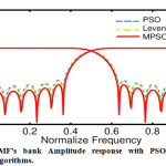 |
Figure 2: QMF’s bank Amplitude response with PSO, MPSO and Levenberga algorithms. |
Table 1: Comparison of performance with other algorithms of proposed MPSO schemes.
| PARAMETERS | [11] | [8] | CWI | LDI | NLI | DI | CFI |
| MPSO | MPSO | MPSO | MPSO | MPSO | |||
| ω | 0.95 | 0.95 | 0.95 | 0.95 | 0.95 | 0.95 | 0.95 |
| eam × 10−2 | 0.45 | 0.67 | 0.63 | 0.98 | 0.332 | 0.828 | 0.789 |
| ep × 10−7 | 0.00742 | 1.69 | 0.0632 | 0.0043 | 0.00123 | 0.0842 | 0.0976 |
| es × 10−5 | 0.127 | 7.49 | 0.00476 | 0.0006 | 0.00315 | 0.0621 | 0.0764 |
| et × 10−8 | 0.0332 | 0.0231 | 0.0454 | 0.0318 | 0.0105 | 0.0267 | 0.0344 |
| As | 36.5 | 36.15 | 35.91 | 35.43 | 37.32 | 35.43 | 35.31 |
| PRE | 0.0102 | 0.0202 | 0.00718 | 0.00904 | 0.00341 | 0.00206 | 0.00338 |
| M SE × 10−2 | 0.02807 | 0.074 | 0.0254 | 0.921 | 0.00126 | 0.0614 | 0.0854 |
| PSNR (dB) | 83.64 | 79.4 | 81.70 | 84.01 | 89.23 | 79.12 | 76.15 |
Reconstruction of Biomedical Image
To measure other parameters of fidelity such as proposed QMF with MPSO mean square error (MSE) and peak signal-to-noise ratio (PSNR), a magnetic resonance imaging (MRI) brain image is taken. For analysis of this image, the sub-band coding is used [1]. Fig. 3(a) shows the selected MRI brain image [23] which is applied at input (x(j, k)) of QMF bank analysis system given in Fig. 3(b). The input image is decomposed into two bands by LPF (H0(Z)) and HPF (H1(Z)) and each signal is decimated by 2. 2 In addition, each decimated sub-band is filtered along column using identical analytical filters leading to quadrature sub-bands again decimated by 2. This second level decomposition of image is labeled as LL2, LH2, HL2, and HH2. These sub-bands may be further processed to obtain amultilevel decomposition as desired in a specific application. For the image under consideration, two-level decomposition is used. The decomposed im-age is transmitted through the channel and the received image is applied to synthesis QMF bank as shown in Fig. 4(a). At output of QMF bank, the reconstructed image (x′ (j, k)) is obtained as shown in Fig. 4(b). Through evaluating the fidelity of the restored signal to original signal, the quality of the proposed method is evaluated The M SE and P SN R fidelity parameters are calculated using following expressions:
![]()
![]()
where M and N are the dimensions of image. A better designed QMF bank should provide lower M SE and higher P SN R. A comparison of M SE of proposed method with other algorithms is also given in Table 1. The MSE performance of proposed NLI-MPSO is far better than the other methods. For image under consideration, the average MSE obtained with NLI-MPSO is 1.26 × 10⁻⁵ as compared to 2.8 × 10⁻⁴ of recently reported Levenberga technique [3]. Moreover, as seen from Table 1, the proposed QMF with NLI-MPSO provides higher P SN R when compared with other techniques. For example, the PSNR of NLI-MPSO is 5 dB higher than that of Levenberga algorithm. Therefore, the proposed technique shows better results over the other algorithms for a biomedical image reconstruction.
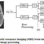 |
Figure 3: (a) Magnetic resonance imaging (MRI) brain image (b) Sub-band coding scheme for image processing |
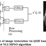 |
Figure 4: (a) Scheme of image restoration via QMF bank (b)Reconstructed image using proposed NLI-MPSO algorithm |
Conclusion
A modified PSO (MPSO) method erstwhile proposed for designing two-channel linear-phase QMF bank. The performance of QMF bank with different variants of MPSO is compared with the famous conventional design methods used by QMF banks. The simulation consequences demonstrate the dominance of suggested strategy in reference to reduced pass-band, stop band, transition band errors, amplitude distortion furthermore peak reconstruction error. The suggested strategy QMF scheme can be effectively applied to improve the fidelity parameters of a biomedical image. For MRI brain image, the QMF with NLI-MPSO algorithm exhibits significant improvement in M SE and P SN R. The proposed MPSO method can therefore be a better choice for QMF bank design for medical image reconstruction.
Acknowledgments
Authors used the data available in [23] for their study and did not collect data from any human participant or animal.
Conflict of interest:
The authors declare that they have no conflict of interest.
Funding source
No funding source available
Reference
- Chandran, S. A novel scheme for a sub-band adaptive beam forming array implementation using quadrature mirror filter banks. Electron Lett 2003;39(12):891–892.
CrossRef - Kumar, A., Singh, G.K., Rajesh, G., Ranjeet, K.. The optimized wavelet filters for speech compression. Springer’s International journal of speech technology 2013;16:171–179.
CrossRef - Yang, P., Yunhui, S., Wenpeng, D., Xiaoyan, S., Baocai, Y..Learn-ing adaptive filter banks for hierarchical image representation. Visual Communications and Image Processing Conference IEEE 2014;:366 – 369.
CrossRef - Vishwakarma, A., Kumar, A., Singh, G.K..A prototype filter de-sign for cosine modulated transmultiplexer using weighted constrained least squares technique. AEU-International Journal of Electronics and Communications 2015;69:915 – 922.
CrossRef - Manoj, V., Elias, E.. Design of non-uniform filter bank with canonic signed digit filter coeffcients. IET Signal Processing journal 2009;3:211- 220.
CrossRef - Upendar, J., Gupta, C.P., Singh, G.K..Design of two-channel quadra-ture mirror filter bank using particle swarm optimization. Elsevier’s Digital signal processing 2010;20:304–313.
CrossRef - Rafi, S.M., Kumar, A., Singh, G.K.. An improved particle swarm optimization method for multirate filter bank design. Elsvier’s Journal of the franklin institute 2013;350:757–769.
CrossRef - Sahu, O.P., Soni, M.K., Talwar, I.. Marquardt optimization method to design two-channel quadrature mirror filter banks. Elsvier’s Digital signal processing 2006;16:870–879.
CrossRef - Kumar, A., Singh, G.K., Anand, R.S.. An improved method for designing quadrature mirror filter banks via unconstrained optimization. Journal of Mathematical Modelling and Algorithms 2010;9:99-111.
CrossRef - Kumar, A., Rafi, S.M., Singh, G.K.. A hybrid method for designing linear-phase quadrature mirror filter bank. Digital Signal Processing 2012;22:453 – 462.
CrossRef - Kumar, A., Singh, G.K., Anand, R.S.. An improved method for the design of quadrature mirror filter banks using the levenbergamarquardt optimization. Springer’s Signal image and video processing 2013;7:209– 220.
CrossRef - Soni, R., Jainb, A., Saxenac, R.. An optimized design of nonuni-form filter bank using variable-combinational window function. AEU-International Journal of Electronics and Communications, (Elsevier) 2013;67.
CrossRef - Kayabol, K., Akman, E.T.. The peak-constrained optimization of stable linear-phase iirprqmf bank. AEU-International Journal of Elec-tronics and Communications, (Elsevier) 2005;59.
CrossRef - Bindiya, T., Elias, E.. Design of totally multiplier-less sharp transition width tree structured filter banks for non-uniform discrete multitone system. AEU-International Journal of Electronics and Communications, (Elsevier) 2015;69:655 – 665.
CrossRef - Tseng, C.C., Lee, S.L.. Design of fractional order digital differentiator using radial basis function. IEEE Transaction on Circuits and Systems 2010;57:1708–1718.
CrossRef - Reddy, G. T., & Khare, N. Hybrid firefly-bat optimized fuzzy artificial neural network based classifier for diabetes diagnosis. International Journal of Intelligent Engineering and Systems, 2017, 10(4), 18-27.
CrossRef - Reddy, G. T., & khare, N. (2018). Heart disease classification system using optimised fuzzy rule based algorithm. international journal of biomedical engineering and technology, 2018, 27(3), 183-202.
CrossRef - Gadekallu, T. R., & Khare, N. (2017). Cuckoo search optimized reduction and fuzzy logic classifier for heart disease and diabetes prediction. International Journal of Fuzzy System Applications (IJFSA), 2017, 6(2), 25-42.
CrossRef - Ghosh, P., Das, S., Zafar, H. Adaptive-differential-evolution-based design of two-channel quadrature mirror filter banks for sub-band coding and data transmission. IEEE Trans Syst Man Cybern 2012, 42, 1613-1623.
CrossRef - Mitra, S.K.. Digital signal processing, a computer based approach. McGraw-Hill 2011;.
- P.P., ,Vaidyanathan, . Multirate and filter banks. Prentice-Hall Engle-wood Cliffs 1993;.
- Ahirwal, M.K., Kumar, A., Singh, G.K.. Analysis and testing of pso variants through application in EEG/ERP adaptive filtering approach. Biomed EngLett 2012;:186–197.
CrossRef - http://wwwwebmdcom/brain/defaulthtm/2013.

