
Manuscript accepted on :23-May-19
Published online on: 25-06-2019
Plagiarism Check: Yes
Reviewed by: Yaswanth Bhanumurthy
Second Review by: Muhammad Shahzad Aslam
M. Purna Kishore1, B. T. P. Madhav1 and S. S. Mohan Reddy2
1Department of ECE, Koneru Lakshmaiah Education Foundation, AP, India.
2Department of ECE, SRKR Engineering College, Bhimavaram, India.
Corresponding Author’s Email: btpmadhav@kluniversity.in
DOI : https://dx.doi.org/10.13005/bpj/1695
Abstract
This article presents a novel elliptical curved coplanar waveguide fed antenna with defected ground. Electromagnetic coupling between splitring resonator (SRR) on other side to the substrate to CPW feeding line on the top side resulting the frequency notches in the wideband. The SRR shaped etched portion in the ground plane not only miniaturizing the antenna, but also providing good bandwidth in the operating bands. Antenna providing multiband characteristics for PCS, Bluetooth, LTE, ISM (Medical Application Band) and Wi-Fi communication (2-3.6 GHz), WLAN IEEE 802.11a/h/j/n (4.5-5.825 GHz), satellite system X-band downlink (7.5-9 GHz) and satellite communication applications at (12-16 GHz) & (17.5-18.5 GHz) respectively. This antenna offering quad band notching with penta band operation from 2-20 GHz. The size of the antenna is 40X44X1.6 mm with peak gain value of 7.18 dB with average efficiency parameter more than 68%. The manufactured antenna prototype is tested for validation and the obtained measurement matching with respect to the optimized simulation result.
Keywords
Coplanar Waveguide; Elliptical Curve; Metamaterial; Multiband Antenna
Download this article as:| Copy the following to cite this article: Kishore M. P, Madhav B. T. P, Reddy S. S. M. Metamaterial Inspired Gain Enhanced Elliptical Curved CPW fed Multiband Antenna for Medical and Wireless Communication Applications. Biomed Pharmacol J 2019;12(2). |
| Copy the following to cite this URL: Kishore M. P, Madhav B. T. P, Reddy S. S. M. Metamaterial Inspired Gain Enhanced Elliptical Curved CPW fed Multiband Antenna for Medical and Wireless Communication Applications. Biomed Pharmacol J 2019;12(2). Available from: https://bit.ly/2J2PTXP |
Introduction
Design of compact antennas with multiband characteristics and high gain is a challenging job to the antenna engineers. In this aspect, antennas with metamaterial loading providing advantages over traditional antennas with their high gain in compact size, high directivity and omni directional radiation pattern.1-3 The metamaterials with negative permittivity and permeability can be used as phase compensator, which will help in design of subwavelength cavity resonators.4-5
The parasitic structures of near field resonance can be obtained with meta-material loading in monopole antennas, but which may lead to narrow bandwidth. To improve the bandwidth, active devices can be used in the antenna structure and a negative permittivity transmission line in the radiating element also can be used.6-10 Many printed antennas are designed and fabricated to obtain dual, triple, quad and penta band characteristics in the literature. Split ring resonators are used in the antenna structure to obtain meta-material properties. The SRR will help in the reduction of the antenna size and it also serves as filtering element.11-14
This paper presents a novel elliptical curved coplanar waveguide fed antenna with SRR shaped defected ground structure. In addition, splitring resonator is placed at opposite surface to the CPW feed. The placement of SRR on the opposite side of the printed antenna results in notch band characteristics. At notching frequency, the degradation of the radiation is because of the magnetic coupling of SRR with electromagnetic signal propagation on the feedline. This coupling is filtering the unwanted frequencies in the operating band from 2-20 GHz and reducing the interference within the wide band.
Antenna Modelling
The current antenna iterations are presented in Figure 1. And the geometry is given in Figure 2. The designed antenna consists of paired elliptical curved radiating elements with slots at the upper portion. A coplanar waveguide feed is used in the structure for simplicity and SRR shaped slots are placed in the ground plane for improving the impedance bandwidth. The split ring resonator slots are in two sizes as shown in the antenna geometry Figures. The final dimensions of antenna is 44 X 40 X 1.6 mm on FR 4 material with permittivity 4.4. The dimensions of the proposed antenna are presented in table 1.
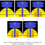 |
Figure 1: Elliptical Antenna Iterations, (a) Antenna 1, (b) Antenna 2, Antenna 3, (d) Antenna 4, (e) Antenna 5.
|
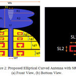 |
Figure 2: Proposed Elliptical Curved Antenna with SRR, (a) Front View, (b) Bottom View.
|
Table 1
| Antenna Parameter | Ws | Ls | R1 | R2 | Lf | Wf | Sl | h | SL1 |
| Dimension | 40 | 44 | 16 | 15 | 24 | 3 | 3.9 | 1.6 | 6 |
| Antenna Parameter | SL2 | SL3 | Lg1 | Lg2 | Lg3 | Lg4 | Sr1 | Sr2 | PL |
| Dimension | 5 | 2.75 | 3 | 4 | 6 | 6 | 2.5 | 1.5 | 14 |
| Antenna Parameter | Sr3 | Sr4 | All dimensions are in mm only | ||||||
| Dimension | 5 | 4 | |||||||
The resonant frequency for square SRR is calculated from
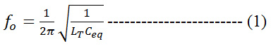
Total equivalent capacitance is Ceq.
Capacitance per unit length
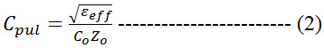
Where Zo is the characteristic impedance, Co is 3 x 10⁸ m/s and εeff is the effective permittivity of the material.
![]()
An additional split ring resonator is placed beneath the CPW feed line on the other side of the substrate to attain notch bands in the wideband. This SRR structure reduces the interference in the wideband and provides multiband characteristics with notching certain unwanted frequencies. This leads to the surface current circulation in the rings and charges accumulates along the gaps to have high capacitance.
Results and Discussion
The designed meta-material inspired antenna is simulated with Ansys HFSS tool and the obtained results are presented in this section. Figure 3 gives the reflection parameter of the antenna related iterations. Antenna 1 to Antenna 5 are resonating at Quad bands with different bandwidth variations between 2 to 20 GHz. The proposed antenna operating in Penta band for PCS, Bluetooth, LTE and Wi-Fi communication (2–3.6 GHz), Wireless LAN IEEE 802.11.a / h / j / n (4.5–5.825 GHz), satellite system X–band downlink (7.5–9 GHz) and satellite communication applications at (12–16 GHz) & (17.5–18.5 GHz) respectively.
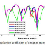 |
Figure 3: Reflection coefficient of designed antenna models.
|
Parametric analysis is done on the proposed antenna model to optimize the final dimensions before fabricating. Figure 4 shows the parametric analysis of the radius ‘R1’ from 14 to 16 mm and obtained the optimized value at 16 mm before fabrication. Another parameter ‘R2’ of elliptical radiating element is optimized with the dimensions of 15 mm which is witnessed in Figure 5.
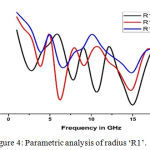 |
Figure 4: Parametric analysis of radius ‘R1’.
|
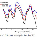 |
Figure 5: Parametric analysis of radius ‘R2’.
|
The width of the feed line ‘Wf’ is changed from 2-3 mm and the optimized dimension is fixed at 3 mm as shown in Figure 6. The parametric analysis of slot length ‘S1’ is presented in Figure 7 and the optimized dimension is 3.9 mm. the optimized dimensions for SRR length ‘SL1’ and slot ‘Lg4’ are presented in Figure 8 & Figure 9. The best results are obtained at ‘SL1’ = 6 mm and ‘Lg4’ = 6 mm are finalized for fabrication.
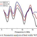 |
Figure 6: Parametric analysis of feed width ‘Wf’.
|
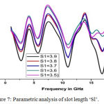 |
Figure 7: Parametric analysis of slot length ‘Sl’.
|
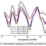 |
Figure 8: Parametric analysis of SRR on back side ‘SL1’.
|
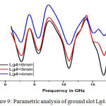 |
Figure 9: Parametric analysis of ground slot Lg4.
|
The designed model three-dimensional radiation is presented in Figure 10 and Figure 11 at 5.8 GHz and 12 GHz respectively. At 5.8 GHz, antenna projecting 5.97 dB gain and at 12 GHz, it is showing 7.18 dB. The radiation pattern in E and H planes is presented in Figure 12 & 13. At 2.5 GHz, the elevation pattern is like monopole radiation and in the azimuthal it is omni directional. At 5.8 GHz, the E–plane radiation is directive and in H–plane it is omni directional with considerable gain. The simulated and measured radiation patterns from antenna measurement setup is matching perfectly for the applicability in the desired operations.
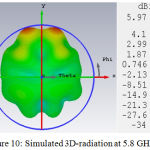 |
Figure 10: Simulated 3D-radiation at 5.8 GHz.
|
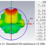 |
Figure 11: Simulated 3D-radiation at 12 GHz.
|
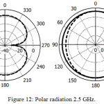 |
Figure 12: Polar radiation 2.5 GHz.
|
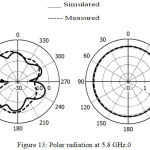 |
Figure 13: Polar radiation at 5.8 GHz.
|
Figure 14 shows surface current distribution at ISM band 2.5 GHz and WLAN band 5.86 GHz. The surface-current concentration is more at ground plane and edges of the patch at 2.54 GHz, whereas surface-current is a little bit high radiating structure at 5.8 GHz.
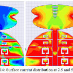 |
Figure 14: Surface current distribution at 2.5 and 5.8 GHz.
|
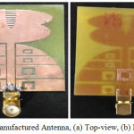 |
Figure 15: Manufactured Antenna, (a) Top-view, (b) Bottom-view.
|
The prototyped antenna front and back view is presented in Figure. 15. Figure 16 gives the reflection coefficient. At lower operating band, a perfect matching of operating bands can be observed and at higher operating band, a small variation is observed due to dielectric loss and SMA connector poor soldering.
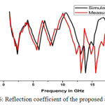 |
Figure 16: Reflection coefficient of the proposed antenna.
|
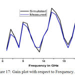 |
Figure 17: Gain plot with respect to Frequency.
|
Frequency Vs Gain and radiation efficiency is presented in Figure 17 & 18 respectively. Peak realized gain of 7.18 dB at 12 GHz can be observed from the Figureure and an average efficiency of 68% can be observed. Figure 19 shows the TDA result for the model with transmitted signal and the received signal response.
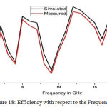 |
Figure 18: Efficiency with respect to the Frequency.
|
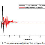 |
Figure 19: Time domain analysis of the proposed antenna.
|
Conclusion
A novel elliptical curve shaped coplanar waveguide fed metamaterial inspired antenna is analyzed and presented in this work. The current antenna providing excellent impedance-bandwidth at the operating bands with peak-gain of 7.18 dB. Antenna operating in different application bands like PCS, LTE, Bluetooth, ISM Band for medical applications, WLAN and satellite communication with directive radiation in elevation plane and omni directional pattern in azimuthal. The average efficiency is about 68%. The dimensions of the antenna are optimized and prototyped antenna is tested on Aniritsu combinational analyzer for validation and the obtained measurement values are similar with respect to the simulation results.
Acknowledgements
We like to acknowledge ECE of KLU and DST for technical support by ECR/ 2016/ 000569 and EEQ / 2016/ 000604.
References
- J Ju et al., “Wideband high-gain antenna using metamaterial superstrate with zero refractive index”, Microwave and Optical Technology Letters, Vol 51, No 8, pp 1973-6, 2009.
- L W Li et al., “A broadband and high gain metamaterial microstrip antenna”, Applied Physics Letters, Vol 96, 2010.
- Y. Dong and T. Itoh, “Miniaturized substrate integrated waveguide slot antennas based on negative order resonance,” IEEE Trans. Antennas Propag, vol. 58, no. 12, pp. 3856–3864, Dec. 2010.
- A. Erentok and R. W. Ziolkowski, “Metamaterial-inspired efficient electrically small antennas,” IEEE Trans. Antennas Propag, vol. 56, no. 3, pp. 691–707, Mar. 2008.
- D. K. Ntaikos, N. K. Bourgis, and T. V. Yioultsis, “Metamaterial based electrically small multiband planar monopole antennas,” IEEE Antennas Wireless Propag. Lett, vol. 10, pp. 936–966, 2011.
- F. J. Herraiz-Martinez, G. Zamora, F. Paredes, F. Martin, and J.Bonache, “Multiband printed monopole antennas loaded with open complementary split ring resonators for PANs and WLANs,” IEEE Antennas Wireless Propag. Lett., vol. 10, pp. 1528–1531, 2011.
- Guohong Du et al., “Multiband metamaterial structure: Butterfly‐pattern resonator”, Microwave and Optical Technology Letters, Vol 54, 2012.
- M shanmughapriya et al., “A Metamaterial Antenna for WSN Applications”, Microwave and Optical Technology Letters,Vol 57, 2014.
- M J Hossaian et al., “Subwavelength operating metamaterial for multiband applications”, Microwave and Optical Technology Letters , Vol 58, 2016.
- Mukesh Kumar et al., “Miniaturization of DNG Metamaterial”, Microwave and Optical Technology Letters, Vol 59, 2017.
- R. Zhao, H.-Y. Chen, L. Zhang, F. Li, P. Zhou, J. Xie, and L.-J. Deng, “Design and Implementation of High Efficiency and Broadband Transmission-Type Polarization Converter Based on Diagonal Split-Ring Resonator”, Progress in Electromagnetics Research, Vol. 161, pp 1-10, 2018.
- B.-Q. Lin, J. Guo, Y. Wang, Z. Wang, B. Huang, and X. Liu, “A Wide-Angle and Wide-Band Circular Polarizer Using a BI-Layer Metasurface”, Progress in Electromagnetics Research, Vol. 161, 125-133, 2018.
- Venkateswara Rao M, Metamaterial inspired quad band circularly polarized antenna for WLAN/ISM/Bluetooth/WiMAX and satellite communication applications, AEU – International Journal of Electronics and Communications, Vol 97, 2018, pp 229-241.
- B T P Madhav, M Venkateswara Rao, Compact Metamaterial Inspired Periwinkle Shaped Fractal Antenna for Multiband Applications, International Journal of Engineering and Technology, Vol 7, Issue 1.1, 2018, pp 507-512.

