
Manuscript accepted on :12-June-19
Published online on: 27-06-2019
Plagiarism Check: Yes
Reviewed by: Mr. Guy-Armel Bounda
Second Review by: Aysegul Kovan
Apurva Bariar1, Siddarth Shetty1, Asavari Desai1 and Raviraja Adhikari2
1Department of Orthodontics, Manipal College of Dental Sciences,Mangalore, Manipal Academy of Higher Education, India.
2Research and Consultancy, Manipal Institute of Technology, Manipal Academy of Higher Education, India.
Corresponding Author E-mail: asavari.laxman@manipal.edu
DOI : https://dx.doi.org/10.13005/bpj/1697
Abstract
Microimplants are widely used to provide absolute anchorage in cases with bimaxillary dentoalveolar protrusion especially in those that require simultaneous retraction and intrusion of anterior teeth. The position of the microimplant significantly affects the build up of stress in the alveolar bone as well as the incisor inclinations, and is therefore a critical factor in treatment plannning. Keeping this in mind, this finite element method(FEM) study was taken up to identify the most suitable combination of implant placement sites for cases in which en-masse anterior retraction is done along with intrusion. The geometric model was constructed from a CBCT scan of the maxilla of an adult patient with full permanent dentition.The images were saved as DICOM files and were later exported to the 3D image processing software (Mimics,version 17). The center of resistance for the 6 anterior teeth was 9 mm superiorly and 13.5 mm posteriorly from the midpoint of crown tip of central incisors. The working archwires were assumed to be 0.019 / 0.025-in stainless steel. The three mini-implant placement sites compared were – S1- Midline micro implant between the maxillary central incisors with two placed posteriorly between maxillary 2nd premolar 1st molar roots. S2 – Micro implant placed between the lateral incisor and canine along with posterior mini implants as above. S3- Micro implant placed high up between the maxillary second premolar and first molar roots. The amount of tooth displacement after finite element analysis was compared with central and lateral incisor and canine axis graphs. For the system S1, intrusive components were seen on the archwire mainly in the anterior region with maximum displacement between central incisors and gradually decreasing away from point of force application. In S2, the intrusive component of force was more evenly distributed. In S3, pattern of intrusive component was similar to S2 but the maximum displacement was slightly lower. Greatest value of minimal principal stress was seen on cervical and apical third of central incisors as well as apical third of lateral incisors in S1; and cervical third of lateral incisors and apical and cervical third of canines in S2. Maximum retraction of anterior teeth was seen in S3. In all of the three systems of force application, tooth inclinations were maintained. Maxillary anterior teeth showed more tendency towards retraction in the case where two micro implants were placed posteriorly high up above the roots of maxillary premolars and molars such that the force is directed diagonally having both horizontal and vertical components, and hence eliminating the need for anterior implants. Greater intrusion tendency was seen when implants were placed between the roots of maxillary central incisors.
Keywords
FEM; Intrusion and Retraction; Mini Implants
Download this article as:| Copy the following to cite this article: Bariar A, Shetty S, Desai A, Adhikari R. Comparative Assessment of Three Microimplant Assisted Biomechanical Strategies for the Simultaneous Intrusion and Retraction of Anterior Teeth in Relation to Alveolar Bone Stress and Change in Incisor Inclinations – A 3D Finite Element Analysis Study. Biomed Pharmacol J 2019;12(2). |
| Copy the following to cite this URL: Bariar A, Shetty S, Desai A, Adhikari R. Comparative Assessment of Three Microimplant Assisted Biomechanical Strategies for the Simultaneous Intrusion and Retraction of Anterior Teeth in Relation to Alveolar Bone Stress and Change in Incisor Inclinations – A 3D Finite Element Analysis Study. Biomed Pharmacol J 2019;12(2). Available from: https://bit.ly/2LoNoBO |
Introduction
Bimaxillary dentoalveolar protrusion is one of the commonest malocclusions encountered by orthodontists worldwide. It is characterized by proclination of maxillary and mandibular anterior teeth with resultant projection of the lips as well as convexity of the profile. It is conventionally treated by therapeutic extraction of the first premolars, trailed by complete anterior tooth retraction to acquire the desired dental and soft tissue profile changes1. Anchorage requirement is critical in such cases and a successful treatment outcome is often dependent on effective anchorage control strategies.2
There are several extraoral as well as intraoral sources of obtaining anchorage. In recent times, skeletal anchorage has almost replaced all other conventional modes of anchorage reinforcement; as it eliminates all unwanted tooth movement thereby leading to superior treatment outcome and greater patient satisfaction. Skeletal anchorage can also be of various types: anchorage obtained with the help of miniplates and with the help of micro implants being the two important ones. Out of the two, the use of micro implants is widespread due to its advantages like ease of insertion, lower predisposition to infection, shorter procedure times and lesser discomfort to the patient.
Achieving simultaneous intrusion and retraction of anterior teeth has always been a challenge for orthodontists. However, with the use of mini implants obtaining good treatment results is possible and much more predictable. This can be done using a number of biomechanical strategies.
Either by using one midline mini implant and two posteriorly between maxillary 2nd premolar and 1st molar roots,
Using two mini implants placed between the lateral incisor and canine alongwith two posterior mini implants as above,
Two mini implants placed posteriorly high above between the second premolar and first molar such as the force is directed diagonally with both horizontal and vertical components.
The stress generated in the surrounding alveolar bone as well as amount of intrusion and retraction varies in each scenario. Hence, selection of the mini implant placement site should be done after careful consideration.
Finite Element Analysis (FEA) is a numerical method for solving problems in mathematical physics and helps in finding analytical solutions for stresses of various objects based on mathematical calculations. Qualitative and quantitative reactions of teeth and alveolar bone to orthodontic forces can be evaluated.
Therefore, this study was taken up with the aim of evaluating and comparing the efficacy of the above mentioned mini implant sites for intrusion and retraction of anterior teeth.
Aims and Objectives
To graphically display the pattern and magnitude of stress distribution along the alveolar bone of maxillary anterior teeth on application of intrusive and retraction forces using microimplants and analyse the efficacy of the three techniques.
Materials and Method
It was a 3D finite element analysis study for which prior ethical clearance was obtained from the Institutional Ethics committee, Manipal College of Dental Sciences, Mangalore. The study was conducted in collaboration with the CAD Lab, Department of Mechanical Engineering, Manipal Institute of Technology.
The FE-analysis consisted of the following steps
Construction of geometric model: This step involved creation of geometric representation of maxillary teeth, alveolar bone, wires and brackets.
Meshing: The geometric model was subdivided into discrete elements and the resulting set was called mesh. ANSYS provides various options to produce 3D mesh on solid geometry of tooth model.
Materials, Loads and Boundary Conditions: In this step, material and element properties along with loads and boundary conditions were defined on discretized model of complete model in ANSYS.
Analysis: In this step FEA solver ANSYS Workbench is used to calculate displacement and stress due to the loading conditions.
Visualisation of the results: This step involves visualization of various results such as displacement, Von-Mises stress and comparison of stress with the design admissible limits of materials.
Construction of Geometric Model
The geometric models of the maxillary central and lateral incisors, canines, second premolars and first molars were constructed using the CBCT scan of the maxilla of an adult patient with full permanent dentition, obtained with Planmeca Promax 3D MID. The images were saved as DICOM files and were later exported to 3D image processing software (Mimics, version 17).
A 3D solid model was constructed encompassing of maxillary dentition, alveolar bone, mini implants, brackets and arch wire (Fig 1,2). First premolar was not constructed in order to simulate retraction as seen in 1st premolar extraction cases. Brackets with slot size 0.022”/ 0.028” were modelled with the Roth prescription and attached to the crowns of the teeth, such that the facial axis point was coinciding with the center of the bracket slot (base point and slot point). Stainless steel arch wire of dimension 0.019” × 0.025” was designed with hook of 8mm between the lateral incisor and canine, for the purpose of retraction.
The tooth model was then exported in STL format.
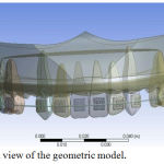 |
Figure 1: Frontal view of the geometric model.
|
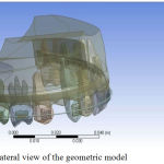 |
Figure 2: Lateral view of the geometric model.
|
Conversion of Geometric Model to Finite Element Model
STL(Stereo Lithography) model data was used to generate suitable mesh. STL is a file format native to the stereo lithography computer aided design programming created by 3D Systems.3MATIC supports this file format and is also generally utilised for rapid prototyping in dentistry. After meshing, the file was exported to ANSYS Workbench where material properties, load and boundary conditions were defined. (Fig 3-5).
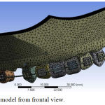 |
Figure 3: FE model from frontal view.
|
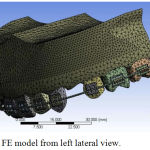 |
Figure 4: FE model from left lateral view.
|
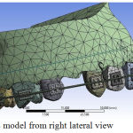 |
Figure 5: FE model from right lateral view.
|
There were 172265 tetra elements and 280942 nodes (Table 1). It is highly impossible to achieve perfect quality parameters for the mesh generated for such complex geometry. However, reasonably good quality parameters were maintained in the model in order to get quality results. Also, special care was taken to model contact between different parts in the model such as contact between arch wire and bracket, contact between teeth and bracket, contact between teeth and the alveolar bone.
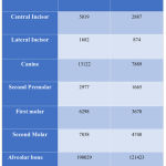 |
Table 1: Finite element details of each component of the model.
|
Material Properties and Data Representation
Non-living mechanical structures for example implants, abutments, and restorations can be mimicked in detail and can significantly impact the computed stress and strain values, similar to living structures. These materials can be carefully demonstrated in FEA templates utilising already decided isotropic, transversely isotropic, orthotropic, as well as anisotropic properties. In an isotropic material, the pertinent material properties are the same every way, bringing about just 2 autonomous material constants, for example, Young’s modulus and Poisson’s proportion. Young’s modulus (MPa), otherwise called the tensile modulus, is a quantity that is used to characterise materials and it is a measure of the stiffness of an elastic material. Young’s modulus is also called the elastic modulus or modulus of elasticity, since Young’s modulus is the most ordinarily used elastic modulus. Poisson’s ratio is the ratio of the contraction or transverse strain (perpendicular to the applied load), to the extension or axial strain (in the direction of the applied load) when a sample object is stretched.When a material is compressed in 1 direction, it has a tendency to expand in the other 2 directions perpendicular to the direction of compression.This phenomenon is called the Poisson effect and Poisson’s ratio is a measure of the Poisson effect.
Most of the elastic properties of selected living and non-living materials are widely available in different material properties database. Young’s modulus and Poisson’s ratio are used in models to reproduce reality as closely as possible. For instance, alveolar bone (both cortical and cancellous portions), implant, abutment, metal framework, and porcelain can be included in the model properties. In the numerical simulation that was performed, stainless steel orthodontic wires and brackets with the above material properties was used Table 2.
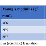 |
Table 2: Material Properties.
|
Defining the Boundary Condition
In order to make the connected nodes between the brackets and archwires deform together, translational degrees of freedom of the arch wire in the two flexural directions were coupled; and in the axial direction of the arch wire, translational degrees of freedom remained unconstrained. This allowed free axial rotation movement of the arch wire, while the friction between the arch wire and brackets along the axial direction was ignored.4 To simulate the constraints of the model, the boundary conditions of alveolar bone was defined to prevent it from free bodily motion. The nodes which were attached to the outer surface area of the bone were fixed in all directions to avoid free movement.
Application of Forces
Three point of force (Loading situation) application were chosen in view of simulated clinical circumstances and focusing on what a clinician for the most part would choose to intrude and retract maxillary incisors. Thus, the points of force application were:
LOAD 1: 120 gm in Z direction (8 mm from the arch wire) and 100 gm parallel to arch wire (S1)
LOAD 2: 60 gm in Z axis (8 mm from the arch wire) and 100 gm parallel to the arch wire (S2)
LOAD 3: 13.5 mm posteriorly and 9 mm superiorly to the incisal edge of upper central incisors at an angle to generate both vertical (60 gm each) and horizontal components (100 gm each) (S3)
Frictional coefficient between the bracket and arch wire slots was assumed to be 0.2.45,46
Results
Stress pattern and deformation in x, y and z axis as well as total displacement were analysed along the alveolar bone of maxillary incisors on application of intrusive and retraction forces using micro implants, using ANSYS workbench.
Because of the action of various components of stresses on the teeth and alveolar bone the results obtained consisted of displacement (Table 3), minimum principal stress (Table 4) and Von Mises or equivalent stress (Table 5).
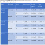 |
Table 3: Recorded directional deformation at crown and root tips in Y and Z axes from different force systems(mm).
|
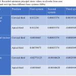 |
Table 4: Recorded minimum principal stress values on alveolar bone near crown and root tips from different force systems (MPa).
|
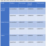 |
Table 5: Recorded equivalent stress/Von Mises stress values on alveolar bone near crown and root tips from different force systems(MPa).
|
For the system S1 with micro implants placed between the central incisors, intrusive component of force was maximum in the anterior region, which gradually decreased away from the force application point (Figure 6). In the second scenario S2 with the micro implant placed between the lateral incisor and canine, the intrusive force was more evenly distributed (Figure 7). In the third scenario S3, pattern of intrusive component of force in the archwire was similar to S2, but the maximum displacement was lesser than in S2 (Figure 8).
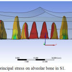 |
Figure 6: Minimum principal stress on alveolar bone in S1.
|
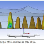 |
Figure 7: Minimum principal stress on alveolar bone in S2.
|
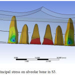 |
Figure 8: Minimum principal stress on alveolar bone in S3.
|
Discussion
One of the major challenges faced by orthodontists is understanding and predicting the complexities involved in the response of teeth to forces and moments.30 Finite element analysis was selected for this study because of its advantages like it is non invasive, three dimensional, can simulate the actual physical properties of the materials involved, visualisation of the actual tooth displacement, measurement of stresses at any point as well as the possibility of infinite magnification.3,34
In order to accomplish an amicable profile in patients with protusive lips, extraction of premolars and retraction with critical anchorage is often necessary.6,45 In such cases, it is important to ensure there is no torque loss with respect to the maxillary anterior teeth. This can be done by incorporating additional torque in the the arch wire, using high torque brackets or by adjusting the length of the anterior retraction hook.47 Another effective way is to use micro implants at appropriate sites. These can be used to control anterior torque as well as conserve posterior anchorage.
During enmasse retraction of maxillary anterior teeth, it is necessary to apply an intrusive component of force to prevent extrusion as well as to maintain the labial crown torque. This can be achieved with the help of micro implants and ARH in sliding mechanics. It is thus important to bring light to the best technique requiring minimum number of micro implants. The best combination of position of OMIs and point of force application that can generate optimum intrusive force is required to control incisor inclination and bring about active intrusion. Initially, there was a need to explore the CR for 6anterior teeth in the model so that force can be applied at or in vicinity of CR. The centre of resistance varies among patients, depending on alveolar bone support, root length and number of teeth.49-53
It is desirable for the line of action of force to pass through CR for the bodily retraction of 6 anterior teeth in en-masse retraction appliances.4 Rigid splinting of incisors and canines should be included in the design to prevent deformation between the main arch wire and the ARH49,52 and a rigid palatal lever arm which is bilaterally connected that can enable force application around the center of resistance without deflection of the ARH and gingival impingement.52,53
Sang – jin Sunget et al in their study applied the intrusive force component of 30 to 60 gms to the tooth centre of resistance of 6 anterior teeth to expect simultaneous movement.3 In our study, 20gms/tooth of intrusive force was used.
Maximum compressive stress on the alveolar bone was found at the cervical and apical third of central incisors in S1, cervical third lateral incisors and canines in S2, apical third of lateral incisors in S1 and apical third of canines in the S3. The torque loss was calculated by measuring the difference between initial and final displacement of crown tip and root apex, if both the crown tip and root apex moved equally it showed the translation i.e. the bodily movement. Inclination of tooth was maintained in all of the three cases described in our study.
In Y axis, crown tip of anteriors showed maximum displacement in S3 showing a greater tendency of retraction. Similarly, displacement at root apex is highest in S1 showing greater tendency towards intrusion as compared to the S2 and S3. Among the anterior teeth, canines showed greatest intrusive tendency.
Maximum total displacement was seen at the crown tip of maxillary anteriors was seen in S2. Root tip of maxillary canines showed maximum total displacement among the anteriors. Extrusion of central incisors, lateral incisors and canines is prevented maximum in S1. Torque loss with the root moving in Y direction was not seen in any of the case. Compressive stress on the labial alveolar bone was seen maximum on the cervical and apical third of central incisor in the S1, apical third of lateral incisor in S1 and apical third of canine in S3.
Finite element method is a powerful tool for the analysis of complex structures, however its outcome is dependent on formulation of the problem.51 When any numerical model is used, choosing the right material properties, such as elastic modulus and Poisson’s ratio, as well as presenting alveolar bone’s characteristics and teeth are the most critical factors in obtaining precise results.
In this study, the greatest value of minimum principal stress was seen on cervical and apical third of central of S1, cervical third of lateral incisors and canines of S2, apical third of lateral incisors of S1 and apical third of canines of S2. Maximum retraction of maxillary anteriors was seen in S3. A significant finding is that torque loss was not seen in any of the three models.
Displacement in Y axis
Force in Y direction (Fy) causes tensile and compressive stresses on the lingual and labial aspect of teeth and alveolar bone. Maximum displacement of the crown tip of central incisors, lateral incisors and canines was seen in S2. This shows a greater tendency of retraction with all anterior teeth showing similar displacement values.
In a study done by Teasoo Kim et al,12 it was found that despite applying the line of action of force close to the centre of resistance of 6 anterior teeth along with adequate amount of intrusive force, the central and lateral incisors were not bodily retracted. In our study,with similar force application, slight labial tipping of the crowns of maxillary anterior teeth were seen.
Diplacement in Z axis
Force in Z direction (Fz) causes tension and compression stresses on teeth and alveolar bone in both the occlusal and apical direction which tends to move teeth in these directions. Apical dispalcement of root apex was highest in S1 showing greater intrusive tendency. Canines among the anterior teeth showed greater intrusive tendency.
In a similar study done by Quiang Zhang et al,14 it was found that loading on lateral incisors was greater than other teeth while retracting the 6 anterior teeth with their force passing near the centre of resistance. In our study,a similar result was found.
Limitations of FEM study
FEM is not an actual simulation, there might be some degree of variation from clinical situation. The result of this study is only valid with patients exhibiting similar bone density, root lengths and angulations, crown sizes etc. also, placing implants very high above the arch wire is not always possible in clinical situations.
Conclusion
This study was carried out to analyse the efficacy of three micro implant assisted biomechanical strategies for simultaneous intrusion and retraction of maxillary anterior teeth.
A three-dimensional finite element model of the maxillary dentition with alveolar bone was created using ANSYS Workbench. Load was applied to the model in three different ways to bring out the desired result.
Conclusions drawn from this study are –
In all of the three systems of force application, tooth inclinations were maintained.
Maxillary anterior teeth showed more tendency towards retraction in the case where two micro implants were placed posteriorly high up above the roots of maxillary premolars and molars such that the force is directed diagonally having both horizontal and vertical components, and hence eliminating the need for anterior implants.
Greater intrusion tendency was seen when implants were placed between the roots of maxillary central incisors.
References
- Kumar PS, Kharbanda OP. Treatment effects of mini-implants for en-masse retraction of anterior teeth. Am J Orthod Dentofacial Orthop. 2009;135(1):5-6-7. doi:10.1016/j.ajodo.2008.11.015.
- Chetan S, Keluskar KM, Vasisht VN, Revankar S. En-masse retraction of the maxillary anterior teeth by applying force from four different levels ??? A finite element study. J Clin Diagnostic Res. 2014;8(9):ZC26-ZC30. doi:10.7860/JCDR/2014/8408.4831.
- Sung S-J, Jang G-W, Chun Y-S, Moon Y-S. Effective en-masse retraction design with orthodontic mini-implant anchorage: A finite element analysis. Am J Orthod Dentofac Orthop. 2014;137(5):648-657. doi:10.1016/j.ajodo.2008.06.036.
- Malkoç S, Öztürk F, Öreki B, Bozkurt BS, Hakki SS. Real-time cell analysis of the cytotoxicity of orthodontic mini-implants on human gingival fibroblasts and mouse osteoblasts. Am J Orthod Dentofac Orthop. 2012;141(4):419-426. doi:10.1016/j.ajodo.2011.12.009.
- Park HS, Bae SM, Kyung HM SJ. Micro-implant anchorage for treatment of skeletal Class I bialveolar protrusion. J Clin Orthod 2001;35417-22.
- Jeong G-M. Finite element investigation of the centre of resistance of the maxillary dentition. Korean J Orthod. 2009;39(3):83-94.
- Sung SJ, Baik HS, Moon YS, Yu HS CY. A comparative evaluation of different compensating curves in the lingual and labial techniques using 3D FEM. Am J Orthod Dentofac Orthop 2003;123441-50.
- Marassi C, Marassi C. Mini-implant assisted anterior retraction. Dental Press J Orthod. 2008;(5):57-74.
- Ammar HH, Ngan P, Crout RJ, Mucino VH, Mukdadi OM. Three-dimensional modeling and finite element analysis in treatment planning for orthodontic tooth movement. Am J Orthod Dentofac Orthop. 2004;139(1):e59-e71. doi:10.1016/j.ajodo.2010.09.020.
- Kim S, Hwang Y, Ferreira A, Chung K. Analysis of temporary skeletal anchorage devices used for en-masse retraction: A preliminary study. Am J Orthod Dentofac Orthop. 136(2):268-276. doi:10.1016/j.ajodo.2007.08.023.
- Assis DSFR De, Xavier TA, Noritomi PY, Gonc AGB. Finite element analysis of stress distribution in anchor teeth in surgically assisted rapid palatal expansion. 2016:1093-1099. doi:10.1016/j.ijom.2013.03.024.
- Kim T, Suh J, Kim N, Lee M. Optimum conditions for parallel translation of maxillary anterior teeth under retraction force determined with the finite element method. Am J Orthod Dentofac Orthop. 137(5):639-647. doi:10.1016/j.ajodo.2008.05.016.
- Zhang DQ, Su JH, Xu LY, Zhong PP. 3D Finite Element Study of En masse Retraction of Maxillary Anterior Teeth in Two Typical Force Directions. :101-107.
- Fer J, Markovi E, Stamenkovi D, Anoel I. Determination of Stresses and Forces on the Orthodontic System by Using Numerical Simulation of the Finite Elements Method. 2012;122(4):659-665.
- Penedo ND, Elias CN, Christina M, Pacheco T, Gouvêa JP De. 3D simulation of orthodontic tooth movement. 2010;15(5):98-108.
- Vakil KK, Sastri MR, Vakil JK. Simultaneous retraction and intrusion using a single palatal micro-implant. 2014;2(3). doi:10.4103/2321-3825.140689.
- Aljhani A, Zawawi KH. The use of mini-implants in en masse retraction for the treatment of bimaxillary dentoalveolar protrusion. Saudi Dent J. 2010;22(1):35-39. doi:2009.12.007.
- Melsen B, Cattaneo PM, Dalstra M, Kraft DC. The Importance of Force Levels in Relation to Tooth Movement. Semin Orthod. 2016;13(4):220-233. doi:10.1053/j.sodo.2007.08.004.
- Chung K-R, Nelson G, Kim S-H, Kook Y-A. Severe bidentoalveolar protrusion treated with orthodontic microimplant-dependent en-masse retraction. Am J Orthod Dentofac Orthop. 2014;132(1):105-115. doi:2005.09.035.
- Chung K, Jeong D, Kim S, Ko Y, Nelson G. En-masse retraction dependent on a temporary skeletal anchorage device without posterior bonding or banding in an adult with severe bidentoalveolar protrusion: Seven years posttreatment. Am J Orthod Dentofac Orthop. 2012;141(4):484-494. doi:.ajodo.2010.06.028.
- Kojima Y, Fukui H. Numeric simulations of en-masse space closure with sliding mechanics. Am J Orthod Dentofac Orthop. 2010;138(6):702.e1-702.e6. doi:ajodo.2010.06.015.
- Lee K, Park Y, Hwang C, et al. Displacement pattern of the maxillary arch depending on miniscrew position in sliding mechanics. Am J Orthod Dentofac Orthop. 2011;140(2):224-232. doi:10.1016/j.ajodo.2010.05.020.
- Orthodontic treatment of Class II malocclusion with miniscrew implants. :1-16. doi:10.1016/j.ajodo.2008.03.013.
- Park Y, Choi Y, Choi N, Lee J. Esthetic segmental retraction of maxillary anterior teeth with a palatal appliance and orthodontic mini-implants. 2007;(Fig 1):537-544. doi:10.1016/j.ajodo.2005.05.051.
- Upadhyay M, Yadav S, Patil S. Mini-implant anchorage for en-masse retraction of maxillary anterior teeth: A clinical cephalometric study. YMOD. 134(6):803-810. doi:10.1016/j.ajodo.2006.10.025.
- Tizini M, Ibrahim G. Retraction of the upper maxillary incisors with corticotomy-facilitated orthodontics and mini-implants. Saudi J Dent Res. 2014;5(2):146-151. doi:10.1016/j.ksujds.2013.10.002.
- Vibhute PJ. Optimizing anterior en masse retraction with miniscrew anchorage. Case Rep Dent. 2011;2011(c):475638. doi:10.1155/2011/475638.
- Carlos A, Ruellas DO, Pithon MM, Lacerda R. Maxillary incisor retraction : Evaluation of different mechanisms. 2013;18(2):101-107.
- Hedayati Z, Shomali M. Maxillary anterior en masse retraction using different antero-posterior position of mini screw : a 3D finite element study. Prog Orthod. 2016. doi:10.1186/s40510-016-0143-z.
- Parashar A, Aileni KR, Rachala MR. Torque Loss in En-Masse Retraction of Maxillary Anterior Teeth Using Miniimplants with Force Vectors at Different Levels : 3D FEM Study. 2014:10-13. doi:10.7860/JCDR/2014/10099.5353.
- Kokich VG. Managing Complex Orthodontic Problems : The Use of Implants for Anchorage. 1996;2(2):153-160.
- Mo S, Kim S, Sung S, et al. Factors controlling anterior torque during C-implant-dependent en-masse retraction without posterior appliances. Am J Orthod Dentofac Orthop. 140(1):72-80. doi:ajodo.2009.09.026.
- G P. orthodontic forces generated by a simulated archwire appliance evaluated by the Finite Element Method. 1987;60.
- McGuinness N. stresses induced by edgewise appliances in the periodontal ligament – a afinite element study. Angle Orthod. 1990;62.
- Melsen B. Biological reaction of alveolar bone to orthodontic tooth movement. Angle Orthod. 1999;69.
- Rudolph DJ, Willes PMG, Sameshima GT. A finite element model of apical force distribution from orthodontic tooth movement. Angle Orthod. 2001;71(2):127-131. doi:10.1043/0003-3219(2001)071<0127:AFEMOA>2.0.CO;2.
- Ren Y, Maltha JC, Kuijpers-jagtman AM. Optimum Force Magnitude for Orthodontic Tooth Movement : A Systematic Literature Review.
- Lee D, Heo G, El-bialy T, Carey JP, Major PW, Romanyk DL. Initial forces experienced by the anterior and posterior teeth during dental- anchored or skeletal-anchored en masse retraction in vitro. 2016;0(0):1-7. doi:10.2319/080916-616.1.
- Article O. Stress distribution pattern in a root of maxillary central incisor having various root morphologies A finite element study. 2012;82(5). doi:10.2319/083111-560.1.
- Uhlir R, Mayo V, Hua P, Chen S, Lee Y, Hershey G. Biomechanical characterisation of the periodontal ligament : Orthodontic tooth movement.:1-10.doi:10.2319/092615-651.1.
- Article O. Effect of the inclination of a maxillary central incisor on periodontal stress Finite element analysis. :3-5. doi:10.2319/100611-627.1.
- Article O. Optimal Loading Conditions for Controlled Movement of. 2009;79(6):1102-1107. doi:10.2319/111608-587.1.
- Kusey RP WJ. comparison of the frictional coefficients for selected archwire-bracket slot combinations in the dry and wet states. Angle Orthod. 1991;61:293-302.
- Kusey RP WJ. Frictional between different bracket-wire configurations and materials. Semin Orthod. 1997;3:166-177.
- CJ. B. The segmented arch approach to space closure. AmJ Orthod. 1982;82:361-78.
- TF. M. Common sense mechanics. J Clin Orthod.
- Ayade V, Annigeri S, Jayade C, Thawani P. Biomechanics of torque from twisted rectangular archwires. Angle Orthod. 2007;77(2):214-220. doi:10.2319/0003-3219(2007)077[0214:BOTFTR]2.0.CO;2.
- Dermaut LR VBM. Evaluation of intrusive mechanics of the type “segmented arch” on a macerated human skull using the laser reflection technique and holographic interferometry. Am J Orthod.
- Pedersen E, Isidor F, Gjessing P AK. Location of centres of resistance for maxillary anterior teeth measured on human autopsy material. Eur J Orthod.
- Melsen B, Fotis V BC. Vertical force considerations in differential space closure. J Clin Orthod.
- Reimann S, Keilig L, Jager A BC. Biomechanical finite element investigation of the position of the centre of resistance of the upper incisors. Eur J Orthod.
- Shroff B, Lindauer SJ, Burstone CJ LJ. Segmented approach to simultaneous intrusion and space closure: biomechanics of the three-piece base arch appliance. Am J Orthod Dentofac Orthop.
- Hong RK, Heo JM HY. Lever-arm and mini-implant system for anterior torque control during retraction in lingual orthodontic treatment. Angle Orthod.

