
Manuscript accepted on :13-Mar-2019
Published online on: 19-03-2019
Plagiarism Check: Yes
Ruchi Agarwal* , C. S. Salimath and Khursheed Alam
Department of Mathematics, School of Basic Sciences and Research, Sharda University, Greater Noida, India.
Corresponding Author E-mail: agarwalruchi205@gmail.com
DOI : https://dx.doi.org/10.13005/bpj/1627
Abstract
Multiple image compression using wavelet based methods including Discrete Wavelet Transform (DWT) through sub band coding (SBC) and decoding are reviewed for their comparative study. True color image compression measuring parameters like compression ratio (CR), peak to signal noise ratio (PSNR), mean square error (MSE), bits per pixel (BPP) are computed using MATLAB code for each algorithm employed. Gray scale image like Magnetic Resonance Imaging (MRI) is chosen for wavelet transform to achieve encoding and decoding using multiple wavelet families and resolutions to examine their relative merits and demerits. Our main objective is to establish advantages of multiple compression techniques (compressions using multiresolution) helpful in transmitting bulk of compressed medical images via different gadgets facilitating early detection and diagnosis followed by treatments or referrals to specialists residing in different parts of the world. Contemporary compression techniques based on wavelet transform can serve as revolutionary idea in medical field for the overall benefit of humanity.
Keywords
Double and Triple Image Compression; Discrete Wavelet Transform; Gray Scale Images; JPEG2000; Lossy Compression; Wavelet Difference Reduction
Download this article as:| Copy the following to cite this article: Agarwal R, Salimath C. S, Alam K. Multiple Image Compression in Medical Imaging Techniques using Wavelets for Speedy Transmission and Optimal Storage. Biomed Pharmacol J 2019;12(1). |
| Copy the following to cite this URL: Agarwal R, Salimath C. S, Alam K. Multiple Image Compression in Medical Imaging Techniques using Wavelets for Speedy Transmission and Optimal Storage. Biomed Pharmacol J 2019;12(1). Available from: https://bit.ly/2HGMqyV |
Introduction
An image is the most important and popular medium of presenting information of every kind. It plays major role in medical field for diagnosis and treatment of almost every disease. An image is formed from pixels that are significantly correlated to each other. Due to this correlation three types of redundancies are observed that play major role in occupying major storage space and slow transmission speed. These redundancies are- Spatial, Temporal, and Spectral Redundancy. Image compression is the solution to overcome these redundancies.
Many algorithm and methods for still image compression are known now days and several articles are published on it. These methods can be selected on the basis of lossy and lossless image compression characterization.1 As the name depicts lossy compression, discards some data permanently to represent the content. Lossless compression does not compromise with picture quality and content. Some of the methods used for lossless compression are entropy encoding; run-length encoding, chain codes and deflate. Lossy compression neglects data that has negligible effect visually and produce content that is physically significant. This type of compression is also known as visually lossless compression (VLC) and is based on tolerance inherent in human vision. Most commonly used methods of VLC are Discrete Cosine Transform (DCT), fractal compression and recently introduced wavelet transform. Image compression scheme based on wavelet contains transformation, quantization, and entropy coding. The transformation part includes discrete wavelet transform and lifting schemes. Some of the quantitative and qualitative image measures involved are: compression rate or bit rate, bits per pixel ratio (BPP), peak signal to noise ratio (PSNR), maximum error, mean square error (MSE), L2-Norm ratio. Other than this, image compression algorithms require different amount of processing power for encoding and decoding the image. Therefore, it is dependent on the machine and choice of compression algorithm. Selection of algorithm for compression depends on viewer’s judgement also which is most important factor in measuring compression in terms of quality, cost, storage, and time.
From last few decades medical imaging has turned out to be a major clinical tool for diagnosis in biomedical field. Large volume of data is executed on per day basis in hospitals and health care institutions through different techniques, like Computed Tomography (CT), Magnetic resonance Imaging (MRI), Positron Emission tomography (PET), Digital Subtraction Angiography (DSA), and Radiography are few to mention. Medical images are termed as combination of low and high frequency data that are highly correlated. Edges present in the image are important perceptually and are presented via high frequency information. In the coming age of telemedicine storing, transmission and reception of digital data without multiple compression would be a tragedy. Therefore, in the following sections medical image is taken as illustrations, which can provide an insight for future technology.
This article is organized as follows: Section 2 presents brief description of different image compression methods employed currently. Section 3 provides a brief outline of the mathematical aspect related to compression using wavelet technology and various parameters to examine the quality of compressed image. Alternative strategies for the enhancement of image quality are also suggested. Section 4 discusses tools and techniques used for compression. Section 5 presents experimental result(s) of multiple compressions using true color and gray scale image using different wavelet families. Finally, section 6 is devoted to results and discussion.
Standardized Methods and Algorithms in Image Compression
With wavelet as the main ingredient, we enter into a dynamic contemporary research environment, what is now referred to as image compression and pattern recognition in medical imaging. Some of the well-known procedures, in practice, for image compression are briefly described below.
Embedded Zero Tree Wavelet (EZW)
The algorithm EZW is based on lossless image compression technique, and enables a scalable image transmission. In EZW embedding process uses bit-plane encoding. In bit plane encoding, image have little bit of significant bits situated in high level sub bands and for this reason wavelet transform is a best choice.2 A key concept of EZW includes hierarchical sub-band decomposition that uses compact multiresolution representation in the image using zero tree coding. During sub-band transformation using wavelet transform, coefficients of filters at low bit rates are zero or almost zero. If the coefficients are represented in the form of a tree then there exists a sub tree in which entire coefficients are zero or approximately equal to zero. These sub trees are termed as zero trees. Non zero coefficients are quantized and then entropy coding is performed using adaptive multilevel arithmetic coding. While encoding a coefficient of significant map, threshold value (T) is pre-decided and coefficients are represented by different symbols that make the coding less complicated.
The main advantage of this algorithm is that it controls bit stream rate precisely, resulting in effective representation of image compression. Scanning order of algorithm EZW is presented in figure 1.
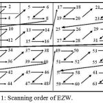 |
Figure 1: Scanning order of EZW.
|
Set Partioning In Hierarchical Trees (SPIHT)
Another wavelet based image compression algorithm is Set Partioning in Hierarchical Trees. It can be considered as refined version of previous method EZW, it initially uses wavelet transform i.e. transmission of information through wavelet coefficients and then finally, important aspect relies on, covering of entire image at one go. This algorithm uses coefficients value repeatedly and hence provides high PSNR with good quality image. It supports lossless compression and is performed in two passes namely sorting pass and refinement pass. In sorting pass as the name defines position of the significant coefficients in the subtree of coefficient node are identified.3 Left out insignificant coefficients is then shifted into a separate list. In refinement pass if the significant bit is greater than T then it is separated form list and decoded. This process is repeated until desired bit rate is achieved. In entire process three lists are used namely: List of insignificant pixels (LIP), List of significant pixels (LSP), List of insignificant sets (LIS). SPIHT executes fast as ordering of coefficients is from maximum to minimum value that makes it energy efficient. Scanning order of algorithm SPIHT is presented below in figure 2.
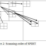 |
Figure 2: Scanning order of SPIHT.
|
Spatial Orientation Tree Wavelet (STW)
Said et al. (1993)4 proposed this algorithm STW that employs method of partitioning of wavelet coefficients. It can be considered as modified form of SPIHT algorithm. The STW algorithm separates all insignificant coefficients on the basis of spatial relationship and maintains a large stack of it. This algorithm forms structured tree consisting of low level coefficients working as a root for the tree. This tree is directed in three different orientations namely horizontal, vertical and diagonal corresponding to their spatial region. These newly formed three descendants are new roots to three full depth spatial orientation trees. In this process these roots serve as high frequency information up to the highest depth in different orientations. It is similar to SPIHT algorithm with the only difference of output coding grouping. For encoding information it is based on state transition model. Basic process of this is: Magnitude grouping of partially transformed image, transmission of coordinates, broadcasting using hierarchical tree structure. This state transition approach employs condensed number of bits for encoding, as spatial portion of transformed value changes its state frequently. Scanning order of algorithm STW is represented in figure 3.
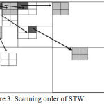 |
Figure 3: Scanning order of STW.
|
Set Partioning In Hierarchical Trees 3D (SPIHT_3D)
Kim et. al (1997) extended SPIHT coding algorithm to SPIHT_3D. In this algorithm coefficient presents in different frequency bands are related in the form of octal tree structure. This algorithm has two passes namely sorting pass and refinement pass.5 All the coefficients forming a spatial orientation tree from all sub bands are basically in appropriate sync with same spatial location in an image. Starting from low sub bands to high sub bands these coefficients are scanned column wise. After this threshold value is selected and correlated to highest coefficient value. Tree containing the biggest value of coefficient set becomes significant. After executing passes and recursive partioning, descendant coefficient which is significant is recognized.
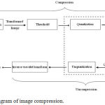 |
Figure 4: Schematic diagram of image compression.
|
This SPIHT_3D algorithm is found efficient in terms of high performance, precise rate regulator, real time applicability for image and video compression.6 The important argument for the thoughtful of the usefulness of these methods, resides in the ability of the wavelets bases, to characterize comprehensive classes of functions in a very tight-fisted way.
Wavelet Difference Reduction (WDR)
James Walker in 2000 developed an image compression coding method based on wavelet. This method can be viewed as advancement over SPIHT because SPIHT deals with the location of significant coefficients that makes the execution of transformed values location identification difficult. WDR involves region of high resolution instead of coefficients and then transformation is obtained. WDR consider indices difference successively instead of location value of significant coefficients. This method uses significant pass that means output of WDR with the sequence of bits, which describes the location of significant coefficients, also contains bits that represent the sign of significant values. It is not capable of giving high PSNR values at low bit rates when compared to SPIHT. This method gives good quality image at high compression ratio, better performance at low bit rates and resolution scalability.3
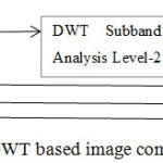 |
Figure 5: A two level DWT based image compression scheme.
|
Adaptively Scanned Wavelet Difference Reduction (ASWDR)
Walker (2000; 2001) proposed enhanced image compression algorithm over WDR that preserves all the features of WDR.7 ASWDR stores the new wavelet coefficients by scanning adaptively to specific image features. This algorithm acclimatizes the scanning order so that it can predict the locations on arrival of new significant values. If forecast is proper and precise then the output will contain sign in place of spatial information of new significant coefficient value. ASWDR adapts the scanning procedure at run time so that location of edge details in an image can be executed properly. In result it increases the edge details in the compressed image. This improves the perceptual quality at low bit rates after compression and advances effects of alteration measure.
JPEG and JPEG2000
The first and well known image compression standard given by working group WG1 of the ISO/IEC joint technical committee 1 is “Joint Photographic Experts Group” mostly identified as JPEG in short. This method is widely known for its lossy compression mode. It was mostly used for storing, transferring compressed images, communicating and editing digital video sequences. In this method sample of blocks are formed and are transformed using discrete cosine transform. The newly formed transformed coefficients are then quantized and coded using Huffman coding. The image compression standard JPEG2000 is advancement over JPEG standard. All facilities provided by JPEG are integrated in JPEG2000 with significant option of lossless and lossy mode, resulting into good quality reconstructed image. It incorporates wavelet based algorithm that executes large blocks in compression process. Precisely, JPEG2000 uses lifting scheme with discrete wavelet transform and biorthogonal basis of Daubechie’s wavelet.
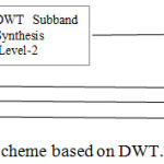 |
Figure 6: A two level image decoding scheme based on DWT.
|
This JPEG2000 standard is currently considered as international standard because of its resolution scalability, multiresolution analysis of discrete wavelet transform, and flexibility of code stream.8 The scalable nature of code stream helps decoding of bits in number of ways like truncation of code stream at any point, using bit plane encoding, resulting into gracefully degraded compressed image with lower resolution.9 In last step, compression is produced using bit stream reassembling that gives desired higher compression. Current computer applications using JPEG2000 algorithm are good in processing large images with low contrast edges for example medical images. The scheme of the algorithm is explained in Figure 7.
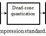 |
Figure 7: Block diagram of JPEG2000 compression standard.
|
Mathematical Framework
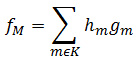
To introduce the mathematical framework of image compression using wavelets let us consider a function f having finite energy. Let’s discuss mathematical form of an image, take L Χ L gray scale image with 256 gray scales. For ≤ x ≤ i + 1, j ≤ y ≤ j + 1 and 0 ≤ i,j ≤ L this image is taken as piece wise constant function f (x,y) = pi,j ∈ N, here 0 ≤ pi,j ≤ 255 defined on a square shaped block. Now, consider an orthonormal wavelet basis of L2 (ℝ) denoted simply by {gm}, m ∈ N. A function f can be represented in basis as follows: f = ∑m∈y {f,gm} gm, here coefficients of function f will be {f,gm}m∈ϒ. Let hm denotes all the coefficients for easier process. The compression task is carried out by selecting a fixed number of coefficients say M. This selection represents that the compression carried out is lossy compression. Let K be the set of indices of the M selected coefficients and fM be the compression obtained. Then,
For compression purpose, wavelet transform can be used in several ways. Nowadays image compression method is built on 2D product basis created from Daubechie’s wavelet. However, fundamental norm of image compression is to reflect compression as an approximation problem. In this regard fix an orthogonal wavelet sayψ. Each wavelet picks information about an image f using its spatial and scaling characteristic, which makes it potentially useful. This gives an idea that focus on the most relevant parts of f. To get the depth of best approximation of f we have to calculate error measure. For this let’s find optimal approximation minimizing the error ||f – fm||2. Value of approximation because of the orthogonality of wavelets equals to
To minimize error non-zero coefficients M those who have largest absolute value should be hand-picked, hence setting
![]()
This then surely yields the desired optimal approximation of f. To apply wavelet transform we consider image in 2D version. The discrete wavelet transform (DWT) is applied to get wavelet coefficient matrix separately in horizontal and vertical directions. To obtain entries of matrix a particular set of wavelet or member of a wavelet family is selected by particular set of numbers, called wavelet filter, coefficients then are arranged in a specified pattern. These data array are decomposed into four sub-bands LL- low pass horizontal and vertical filter, LH- low pass vertical and high pass horizontal filter, HH- high pass vertical and horizontal filter, HL- high pass vertical and low pass horizontal filter. The order of horizontal and vertical filters can be switched to get different representation but it yields same effect on final image. The schematic diagrams of decomposition (analysis) and reconstruction (synthesis) of a signal are provided in Figures 5 and 6.
If it is required to assess the quality of compression, then following performance (measurement) indices are used.
Measuring Quantities (Qualitative and Quantitative Analysis)
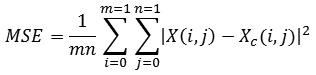
Mean Square Error (MSE): As the name implies, it is square of difference between original and image approximation divided by the number of elements. Mathematically it is given as:
Maximum Error: Absolute deviation taken as maximum in the image compression is termed as maximum error or max error.
Bits per pixel ratio (BPP): Taking one byte per pixel (8 bits), BPP is calculated by multiplying compression ratio with 8. It is basically the number of bits required to store one pixel of any image. For true color image BPP is 24. If the bit rate increases, it results into improvement in quality of the reconstructed image.
Compression Ratio (CR): It is the ratio defined by number of elements present in original image by number of elements present in compressed image. It represents that CR% of original size is stored in the form of compressed image.
L2-Norm Ratio: It is a ratio of the squared L2 norm of the compressed image to the input image. The image is altered in the form of column vector before executing the L2-norm.
Peak Signal to Noise Ratio (PSNR): It measures peak error and is expressed in decibels. It is the ratio between greatest attainable power of signal and the power of noisy signal.10 Higher value of PSNR depicts the better quality of compressed or reconstructed image. PSNR is helpful when image is expressed in bits per pixel. When pixels are represented using 8 bits per sample then n = 8. It is defined as follows:
![]()
Here, MSE represents Mean Square Error and n represents bits per sample.
Compression Using Wavelet Packets
Other than wavelets further recommendations are given for the use of wavelet packets. All the choices definitely play an effective role in performance of image compression ratio, other performance measures and finally on rendered reconstructed image. These algorithms of de-noising and image compression can easily be extended to wavelet packet bases. These extensions are basically useful in multiple image compression. When compared to wavelet bases corresponding wavelet packet bases are utilized to its full capacity of compressibility by a fixed orthogonal wavelet.
Compression Using Bi-Orthogonal Wavelets
There are wavelet bases in which the restriction of ortho-normality is relaxed. In this case one typically uses two different “dual” wavelets
![]()
such that
![]()
unless j = j′ and k = k′. The approximation order of the scheme that approximates functions f by linear combinations of the ψj,k is then governed by the number of vanishing moments of ψ, such wavelet bases are called biorthogonal. They have the advantage that the basic wavelets
![]()
can both be symmetric and concentrated on an interval, which is impossible for orthonormal wavelet bases other than the Haar wavelets.
Tools and Techniques
One of the efficient and important image compression tools is discrete wavelet transform (DWT). It filters the given image at each resolution level into coarse approximation and detailed information. It further decomposes the approximation into next stage containing approximation and detail. This procedure goes on till the desired level is achieved. DWT for many natural image classes provides good compaction properties with low implementation cost.11 Basic requirement in multiple image compression is decomposition of images up to certain level. Therefore, Different wavelets are employed in decomposition of MRI images. General method applicable for multiple compressions is described in figure 4.
Verbally, to start with image compression, firstly decomposition took place on an orthogonal or biorthogonal wavelet basis with the help of discrete wavelet transform. Using threshold parameters certain part of coefficients are selected, while preserving intact the approximation coefficients of an appropriately selected level. Quantization of selected coefficients finishes off compression and in the end for storage or transmission purpose these are encoded. Image decompression process inverts these operations as far as possible. From the decoded and un-quantized coefficients an image is rebuilt by applying inverse discrete transform. The image obtained is thus the reconstructed image. It has been known that compression of image reduces number of bits for minimal storing, speedy transmission, less correlation between neighboring pixels and hence decreases redundant information. These compressed images are decompressed to get the reconstructed image using inverse coding.
Transformation
As mentioned before, input image neighboring pixels are correlated this increases lot of redundant and irrelevant data which results into increase in size of image. Therefore, first step is to reduce the image size by removing redundant information and de-correlating the pixels through thresholding. Transformation of image using some pre-defined methods is utilized for this purpose. Some of the transformations reduce the size in such a way that only few bits are required to represent the image. Various applications are employed directly and indirectly to serve this purpose, some of them are: Discrete Fourier Transform (DFT), Short Fourier Transform (SFT), Discrete Cosine Transform (DCT), Hadamard-Haar Transform (HHT), Slant-Haar Transform (SHT), Karhune-Loeve Transform (KLT), and Discrete Wavelet Transform (DWT).12 In this article DWT is employed and different wavelet families are considered for the purpose of comparative study. This could help in selecting appropriate wavelet basis to achieve twin goals: to economize on memory space and to accelerate transmission.
Thresholding and Quantization
Once DWT is performed, the next task is thresholding which is neglecting certain wavelet coefficients. For fulfilling this purpose one has to decide the value of the threshold and how to apply the same. This is an important step, which affects the quality of the compressed image. The basic idea is to truncate the insignificant coefficients, since the amount of information obtained from them is negligible. Remaining samples are quantized spatially and amplitude wise, by quantization factor. Basically, it is the process of mapping continuous set of input values of image data to countable small set of output values. In thresholding process some samples are eliminated if the amplitude of samples is below threshold predefined value.13 Because of these two factors quality of an image degrades every time, whenever these processes are repeated. Predefined threshold value is responsible mainly for image quality and so is quantization factor. Lots of data is neglected if these processes possess higher predefined values. Values should be chosen in a manner such that it gives good perceptual quality of an image, better compression ratio and minimal loss of information. For multiple compressions these values must be chosen carefully.
Entropy Encoding
Image processing application use entropy based criteria in which best basis is selected that has linear computational complexity. Entropy encoding is the last component in the compression model. This is a lossless technique which aims at eliminating the coding redundancies. A few coding techniques are 1) Run length encoding 2) Differential Pulse coding 3) Huffman coding, In short, quantized values are further compressed by entropy encoder for better compression. This process helps in removing redundancy produced at the output of quantization. With the help of some predefined method, probabilities are assigned to each quantized value. Then code words are used that are assigned to corresponding symbols depending upon the probability related to symbols. Next it converts the input stream into reduced output code stream utilizing suitable code related to assigned probabilities. Thus, it reduces number of bits into optimal bits that are helpful in representing the image.14 Entropy coders mainly used are: Arithmetic encoder and Huffman encoder. Algorithms employing wavelets uses arithmetic code as it allows fractional number of bits in encoding. The Huffman encoder uses integral number of bits for each code. For reconstruction of image decoder step is involved that exactly reverses the encoding operation.
Let image decomposition coefficients of an image for particular choice of the wavelet packet basis be {vi}. Non negative quantity ∈2 ({vi}) defined as entropy, associated with each set of decomposition coefficients {vi} is defined as follows:
![]()
Here,
![]()
In terms of entropy, basis is said to be best if it produces least entropy. This defined entropy gives a measure of a number of components needed to represent the image in a particular basis. For example, if decomposition in a particular basis produces all zero coefficients except one, showing that image coincides with a waveform then it means that entropy reaches its minimum value of zero. On the other hand, if in some basis, the decomposed non-zero coefficients are all equally important say
![]()
then entropy in this case is which is maximum. Here N is the length of data. These are two extreme cases in between which other decomposition will fall. Eventually, what matters most is smaller entropy that leads to fewer significant coefficients required to represent the image.
Experimental Results
Implementation of Triple Compression
Let us consider a true color image of a fruit given below in figure 8. Multiple compressions is implemented on true color fruit image using code that employs Haar wavelet transform at decomposition level 4 with 12 maximum loops in MATLAB software. Results of different compression algorithms with Haar wavelet transform decomposition (initiated in early stage) applied on a fruit image are compiled in the form of a table 1 shown below.
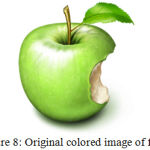 |
Figure 8: Original colored image of fruit.
|
Different algorithms used are: Wavelet Difference reduction (WDR), Adaptively scanned wavelet difference reduction (ASWDR), Embedded zero tree wavelet (EZW), Spatial – orientation Tree wavelet (STW), Set partitioning in hierarchical trees (SPIHT), Set partitioning in hierarchical trees 3D for true color images (SPIHT_3D).
From table 1, it is clear that in multiple compressions PSNR value increases down the column, for every algorithm used on the image. Value above 40 is considered to be good however images in table 2 depicts that major part of reconstructed image fades away. Compression ratio in increasing compression frequency does not hold good percentages; however mean square error is reduced drastically in further compressions. Bits per pixel values are reaching to approximate zero. All these numbers show that there will be considerable loss of data if further compression is followed. This could be taken as an advantage in a scenario where lossy data is preferred. Following table 2 depicts the reconstructed image at every intermittent compression frequency.
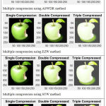 |
Table 2: Multiply compressed images using different compression methods.
|
Compression in Medical Imaging (Triple Compression)
Dataset
For the illustration purpose MRI database is considered.15 This MRI database is a comprehensive collection of many images of stable and unstable patients in intensive care units.
A study was performed on magnetic resonance angiography of cardiopulmonary vasculature with the help of 1.5T General Electric (GE) signal imaging system. Derived images depict coronal slices obtained from consecutive anteroposterior positions within torso. These images contain many frames one of them is taken randomly for compression application, presented in figure 9.
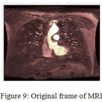 |
Figure 9: Original frame of MRI.
|
Table 3 shows single, double and triple compression of MRI image using Haar, Daubechies, Symlet, Coiflet, and Biorthogonal wavelet families. Method employed for compression is WDR with 12 maximum loops. With the help of Matlab coding and decoding software, details related to these compressions are summarized in table 4.
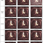 |
Table 3: Multiple compression of MRI using different wavelet families (qualitative analysis).
|
Compression using Haar Wavelet Packet
Wavelet packet technique is also used to compress the image frequently. Given table 5 shows the effect of compression on MRI using Haar wavelet packet at level 4. Using Shannon entropy and selecting balance sparsity-norm thresholding method, multiple compression observations are recorded that are presented in table 6. In similar manner other wavelet family member can be used in place of Haar wavelet.
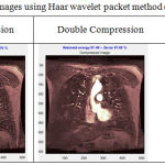 |
Table 5: Multiple compression images using Haar wavelet packet method (qualitative analysis).
|
Results and Discussion
In results obtained in Table 1, the emphasis is on the algorithms employed rather than the role played by wavelets. It could be seen that Peak to Signal Noise Ratio (PSNR) and Mean Square Error (MSE) values remain almost same for different frequency of compression in different methods. However, in a solo algorithm, values of MSE in successive frequency of compression have shown major change resulting into increased value of PSNR irrespective of method employed. As the value of PSNR increases picture quality becomes better. Values of Bits per pixel (BPP) do not show much variation when compared to other measures. Another important aspect of measure is compression ratio (CR) which shows considerable deviation in successive compression in all the algorithms. From the value of CR it can be understood that further compression will not be of good practice as picture quality will degrade and final output will not be of any use. Above all reconstructed image is dependent on the input of picture quality. Clear and original picture will have good results irrespective of any wavelet methods employed for first few compression frequencies.
From table 4 we examine the choice among wavelets, to rate most appropriate mother wavelet for multiple image compression. Following three wavelets – Haar wavelet, Daubechies type 4 and Bi-orthogonal wavelets are the best performers when compared with other wavelets. These wavelets give almost similar results in all aspects of measure. Biorthogonal wavelets are mainly resourceful for compression because the examination part (decomposition) and the synthesis part (reconstruction) are treated by two distinct wavelets.
It is known that PSNR values for lossy compression lies between 30 and 50 dB. It can be perceived from table 4 that PSNR value is greater than 40 dB, this concludes that compressed images of MRI are indistinguishable. During triple compression mean square error is reduced to almost zero, maximum error between compressed and original image is also considerably low when compared with single and double compression values. Further values of measuring parameters at triple compression also show appreciable enhancements. Quality wise images at multiple compressions can be considered as faultless, and seamless for treatment purpose. However, further frequency of compression can lead to loss of considerable amount of data that can be a big loss in terms of consultation procedure. Therefore few frequencies of compressions can be considered in terms of storage, transmission and speedy procedures.
From images obtained multiple compressions in table 5, it can be concluded that single compression is better as compared to further compressions. Triple compression shows slightly blurry picture, this gives an idea that further compression with Haar wavelet packet will loose considerable amount of data and hence advisable to hold on the compression frequency until the data is easily reflected from image. This fact can be clearly grasped from table 6. As global threshold value increases, number of zeros or retained energy is reduced.
Recent standard of image compression JPEG2000 is also applied on MRI sample image and it was found, when compression rate is specified explicitly then significant quality and rate of measurement at certain level is degraded, refer table 8 and 10. However, when compression is performed considering CR values (randomly taken by software) implicitly, quality of image and measuring parameter doesn’t show much change, refer table 7 and 9. In both the scenario PSNR value after single compression is high, depicting acceptable compression in both procedures.
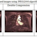 |
Table 7: Multiply compressed images using JPEG2000 algorithm.
|
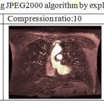 |
Table 8: Image Compression using JPEG2000 algorithm by explicitly giving compression ratio.
|
Conclusion and scope for future work
A comparative analysis in terms of performance parameters like PSNR, MSE, CR and BPP is carried out for true color image and a gray scale image from medical field to highlight relative advantages of image compression modalities using wavelets. Result(s) from this investigative study can be helpful in determining the optimal wavelet basis and level of resolution for minimum storage space and speedy transmission/retrieval of data. At very low bit rates, coding of lossy compression scheme shows blurry part in background. It results when high frequency detail of the image is neglected. This is unavoidable at very low bit rates, however if visual and important part of the image gives the good understanding of content then this part of detail that is giving blurry information can be neglected. Some of the advantages and disadvantages of compression methods used in this article are as follows:
EZW uses predefined scanning order and concept of zero trees however transmission of spatial property of coefficient is absent. From table 1 it can be viewed that compression ratio, using EZW method, for multiple compression decreases leisurely that gives the idea of less compression made to images in multiple calls. SPIHT: It is widely used for image compression. It employs advanced and rooted transmission but still perceptual quality is not up to the mark. Due to this memory utilization is additional. Spatial property of significant positions is recorded implicitly. Because of its hierarchical trees are set portioned, this method is also applicable to natural images. WDR: This method is advancement over SPIHT in terms of better quality of image perceptually, algorithm complexity, higher edge association and better edge safeguarding. Best part is that it suits medical images having low resolution and hence operational on compression process at low bit rate. Only disadvantage is that this method has PSNR either equal or less than SPIHT method. ASWDR: This method is modified version of WDR and has better appreciable qualities like encoding more significant values, better PSNR, better perceptual image quality, presentation of slightly more fine details, higher edge correlation. It is applicable on high compression ratio images like medical images.
The advantages of DWT have resulted in its acceptance as the coding technique in JPEG-2000, the latest standard in still image compression. JPEG-2000: Although JPEG-2000 has started gaining popularity globally in multiple compression process, simulation shows that if MSE for intermittent compression of two images are same then in some conditions further compression procedure degrades the quality of reconstructed image when compared to JPEG procedure.16 Quality of reconstructed image after multiple compression process of JPEG -2000 totally depends on the choice of wavelet filters.
Enormous literature on compression using different wavelet based algorithms is made available in the last couple of decades. Very recently new method is developed based on wavelet known as Geometric wavelet (GW). GW has better PSNR values when compared to earlier methods. Due to advancement in computational cost and efficiency, execution time and code operation complexities can be removed in near future that arises in new developed algorithms.
Main aim of comparative study was storing and transmitting large volume of data that can be helpful in health care sector. Techniques based on wavelet transform occupies less computer memory than conventional methods for image storage, this is noticeably good part for storage of bulk of medical images. These applications due to their versatility can be used in mobile technologies, laptop, desktop, palmtop and notepads in future for speedy treatment. E-health services will become the option for medical communication system that will be successful, inevitable and cost effective.
References
- Salomon D. Data Compression: The Complete Reference, Springer international Edition. 2005.
- Creusere C. D. A new method of robust image compression based on the embedded zero tree wavelet algorithm. IEEE Trans. on Image Processing. 1997;6(10):1436–1442.
- Ravichandran D.,Nimmatoori R., Dhivakar M. R. A. Performance Analysis of Wavelet based Medical Image Compression using EZW, SPIHT, STW and WDR Algorithms for Cloud Computing. Journal ijacect. 2016;5(2):
- Said A and Pearlman W. A. A new, fast, and efficient image codec based on set partitioning in hierarchal trees (SPIHT). IEEE Trans on Circuits and Systems for Video Technology. 1996;6(3):243–250.
CrossRef - Kim B. J., Pearlman W. A. An Embedded Wavelet Video Coder Using 3-Dimensional Set Partitioning in Hierarchical Trees (3D-SPIHT). In Proc. of Data Compression Conference 1997, Snowbird, USA. 1997;251−260.
- Kim B. J., Xiong Z., Pearlman W. A. Low Bit-Rate Scalable Video Coding with 3-D Set Partitioning in Hierarchical Trees (3-D SPIHT). IEEE Transactions on Circuits and Systems for Video Technology. 2000;10:1374−1387.
- Walker J. S., Nguyen T. Q. Adaptive scanning methods for wavelet difference reduction in lossy image compression; Proc. International Conf. Image Processing,Vancouver, Canada. 2000;182-185.
- Salimath C. Wavelets: Algorithms and Applications in Science and Technology ICMSDPA12, Conference Proceedings. 2012.
- Jose B. R. J. The JPEG 2000 Compression standard; Advanced Mathematics Master Universitat de Barcelona, Barcelona; Thesis. 2015.
- Usman A. K., Sahar A., Tahir R. S and Shayan Q. Wavelet Based Image Compression Using Different Techniques: A Comparative Study. International Journal of Electronics & Communication Technology, Signal Processing. 2014;3:144- 149. November 5.
- Mertins A. Image compression via edge-based wavelet transform. Optical Engineering 1999;38(6):1.
CrossRef - Antonini M.,Barlaud M.,Mathieu P & Daubechies I. Image coding using wavelet transform. IEEE Transactions on image processing. 1992;1:2.
CrossRef - Rehna V. J and Kumar M. K. J. Wavelet Based Image Coding Schemes: A Recent Survey. International Journal on Soft Computing (IJSC). 2012;3:3.
CrossRef - Salomon D. Data Compression: The Complete Reference; Springer international Edition. 2005.
- Goldberger A. L., Amaral L. A. N., Glass L., Hausdorff J. M., Ivanov P. C. h., Mark R. G., Mietus J. E., Moody G. B., Peng C. K., Stanley H. E. Physio Bank, Physio Toolkit and Physio Net: Components of a new research resource for complex physiologic signals. Circulation. 2000;101(23):215-e220. http://circ.ahajournasls.org/cgi/content/full/101/23/e215; June doi: 10.13026/C2001G.
- Rajan L. J.,Rabbani M., Margaret A. L. Comparison of multiple compression cycle performance for JPEG and JPEG 2000; Proceedings of SPIE – The International society for optical enginnering 2000;4115. DOI: 10.1117/12.411570.
CrossRef

