
Manuscript accepted on :
Published online on: 21-11-2015
Plagiarism Check: Yes
D.M Mikhaylov, G. N. Lebedev, T. R. Khabibullin, A. F. Shayakov, E. S. Zharikov, A. O. Anpilogov, V. B. Kholyavin, M. N. Yokhin
National Research Nuclear University “MEPhI” (Moscow Engineering Physics Institute), Kashirskoe highway, 31, 115409, Moscow, Russian Federation
DOI : https://dx.doi.org/10.13005/bpj/639
Abstract
Control systems for wireless endoscopic capsules play a very important role as they help to stop the capsule in the exact part of patient’s digestive system for more detailed examination. This paper deals with the draft design for magnet control system of the wireless endoscopic capsule. Calculations for two different cross-sections of coil (square and rectangular) are presented. Analysis of copper wire and copper tube usage for control system is made. Previous developments differ from the present article about control system of endoscopic capsule, which is controlled by the external magnet field. An approach, presented in the article, helps to provide more accurate and quick magnet field change, while system fault tolerance increases.
Keywords
endoscopic capsule; control systems; magnet field; coil; copper tube; copperwire
Download this article as:| Copy the following to cite this article: Mikhaylov D. M, Lebedev G. N, Khabibullin T. R, Shayakov A. F, Zharikov E. S, Anpilogov. A. O, Kholyavin V. B, Yokhin M. N. Development of Draft Design for Magnet Control System of Wireless Endoscopic Capsule. Biomed Pharmacol J 2015;8(1) |
| Copy the following to cite this URL: Mikhaylov D. M, Lebedev G. N, Khabibullin T. R, Shayakov A. F, Zharikov E. S, Anpilogov. A. O, Kholyavin V. B, Yokhin M. N. Development of Draft Design for Magnet Control System of Wireless Endoscopic Capsule. Biomed Pharmacol J 2015;8(1). Available from: http://biomedpharmajournal.org/?p=1188 |
Introduction
At present, a lot of attentionis paid to control systems of wireless endoscopic capsules, because they help to stop the capsule in the exact part of the digestive system for more detailed examination. There are different approaches to control, for example, in [1] expandable capsule is described made of the electroactive polymer, which changes its size when electric current is applied. But control systems are often built on the basis of magnet field usage.
Magnet systems for wireless endoscopic capsules control are described in many patent claims (descriptions) and scientific articles. For example, Sun et al. describe multi-applications of a magnet configuration in actuating wireless capsule endoscope [2]. Lien et al. propose a capsule endoscope magnetic control system [3]. Wakefield tells about magnetically propelled capsule endoscopy provides for the medical examination and treatment of the gastrointestinal tract, reproductive tract, trachea, lungs, vascular system or any accessible body cavity [4]. Kim et al. present a modified magnetic capsule endoscope that can be fixed inside the stomach and to monitor the gastric motility [5].
The described methods differ from the one, described in this article. The developed solution helps to provide more accurate and quick magnet field change (in this case magnetic field distribution can be stable and can guarantee, that the capsule will move in the required direction and with the necessary speed), system fault tolerance increases.
Control system development should be based on the results of detailed numerical modeling and prototype creation, which helps to check modeling results, to work in practice developed approaches to issue resolution and form general technical specifications for the system.
Materials and Methods
To evaluate sample coil parameters it is necessary to estimate, which fields and field gradients are required for creation of efforts and moments, which can move and spin the coil.For this purpose preliminary analytical estimations were made. To solve the issue at first it is necessary to make some resistance to motion of the capsule to simulate the movement within intestine. At second, on the first stage it is convenient to compensate gravity to take into account only the interaction between the magnet field and the environmental resistance. That is why on this stage it is more preferable to put the capsule with some thick liquid, like glycerin. Thus, to evaluate the necessary power for capsule movement it was considered that is can be compared with thick friction force within the liquid [6]:
Ffr= 3πdνη (1)
where d is a capsule diameter equal to 0.012 m, movement speed (ν) equals10 mm/sec (this speed is enough to move through 4-5 m tract for a reasonable amount of time), η – dynamical liquid viscosity.
Means, for glycerin with viscosity 1480* Pa*secat a temperature of 20°С the friction force will be:
Ffr= 3*3.14*0.012(m)*0.01(m/sec)*1480* (Pa*sec) = 1.67* Н = 0.167 g.wt
Let us assume that some threshold value of force is equal to 0.2 g.wt.To determine the limit spin moment produced by the magnet field, let us evaluate the moment of a couple for friction force, evaluate the moment of a couple for friction forceaffecting the capsule, which is spinning around the axis perpendicular to the symmetry axis:
Nfr= 2*Ffr*L/2=3πdνη*L (2)
where L is the length of the capsule, thus:
Nfr = 0.167(g.wt)*3(sm) = 0.5 g.wt*sm.
Now for the evaluated limit values of force and moment let us calculate the coils parameters. Consider that the working volume, where the capsule will be places, is a cube 200 mm on a side. Because it was necessary to preliminary evaluate the coils parameters, we assume a coil with one circular turn with the current.
Field of circular turn axis depends on the distance from the turn center [7]:
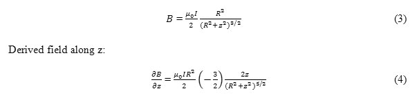
Let us make a diagram of this dependence for the case, when the coil is recorded. In Fig. 1 the dependence of coefficient before μ0I/R2 from the distance along Z axis between the coils in coil radius units; one turn is powered with current and is situated in -1 coordinate of coil radius.
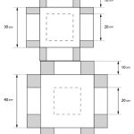 |
Figure 1 |
To determine power characteristics of the coil it is necessary to take into consideration the least force influencing a dipole. This force is influencing the dipole placed in the furthest dot from the “pulling” coil with the least gradient on the distance of two coil radiuses. Zero gradient in the center of the turn was not taken into consideration, because this dot is knowingly placed outside of the working area.
Further magnetic moment for the magnet was determined. The magnet placed inside the capsule will be considered in approximation of the magnet dipole with the magnet moment and will be calculated according to the formula:
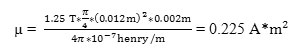
where Br is a remanent magnetic induction of the N38 magnet equal to 1.25 T, and V is the magnet’s volume, therefore the magnet moment equals:
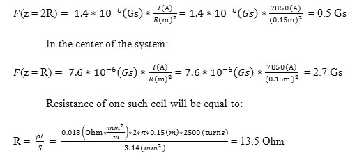
Let us put the force expression, which affects the dipole and is situated on the symmetry axis in the center of the system and in the center of the opposite turn without power (z = 2R) depending on the number of ampere-turns and turn radius:
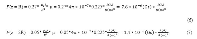
Results
Consider next several coil systems: two systems made from the copper hollow tube 6.35 mm in diameter, two systems made from copper wires 1 mm in diameter and two systems made from the copper wire 2 mm in diameter.
- Copper hollow tube. Characteristics:
- Coil cross-section 5 smx 10 sm.
- Innercoildiameter – 20
- Outercoildiameter – 30 sm.
- Mid diameter– 25 sm.
- Diameter – 3/8 inches or 6.35 mm in diameter.
- Thickness – 0.76
- Wire section– 7.12mm2.
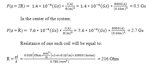
Horizontal slice of coil system with 5sm x 10 smsection is presented in Fig. 2.
Depending on the gap between the tubes, the following numbers of turns can be evaluated with 10 x 5 smcross-section (Table 1):
Without additional cooling the 100 A current can flow through such tube. For example, if 100 A current is used, than with the most density packaging of 100 turns, 10kA-turns can be taken as well as force on the boarder:
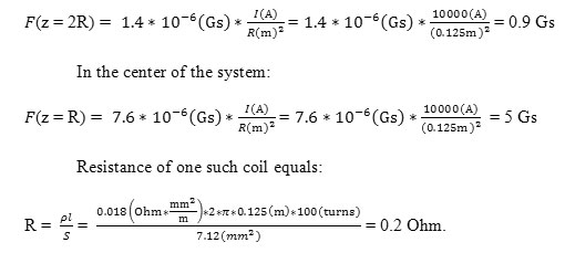
Current source strength:
P = I2R = (100A)2* 0.20 hm=2000Wt
Power voltage:
U = IR = 100 А* = 20 W
2. Copper tube. Characteristics:
- Coil cross-section 10sm x 10 sm.
- Coil made with copper tubes.
- Inner coil diameter – 20
- Outercoildiameter – 30
- Diameter – 3/8 inches or 6.35 mm in diameter.
- Thickness – 0.76
- Cross section – 7.12mm2.
- Middiameter– 30
Horizontal slice of coil system with 10 sm x 10 sm section is presented in Fig. 3.
Depending on the gap between the tubes, the following numbers of turns can be evaluated with 10 x10 sm cross-section (Table 2):
For the same 100Аand coil radius equal to 15 sm the following force will be on the boarder:
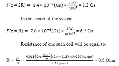
Current source strength:
P = I2R = (100A)2* 0.50 hm=5000 Wt
Power voltage:
U = IR = 100 А* 0.50hm = 50 W
In comparison to the previous case, it is clear that we need twice the amount of copperwire and the force has raised only by 20%.
3. Copper wire with 1 mm in diameter.Characteristics:
- Coil cross-section 5smx 10 s
- Inner coil diameter – 20
- Outercoildiameter – 30
- Mid diameter – 25
- Wire diameter – 1
- Wire section = 0.785mm2.
- Number of turns = 50*100 = 5000 turns.
Horizontal slice of coil system is presented in Fig. 2.
If current density is equal to 1А/mm2, means this density will be taken for evaluation of the corresponding transformer coils, so the current equal to 0.8A will flow; force at the boarders of the working volume will be equal to:
Current source strength:
P = I2R = (0.8A)2* 900 m=57.6 Wt
Power voltage:
U = IR = 0.8 А* 900m = 72 W
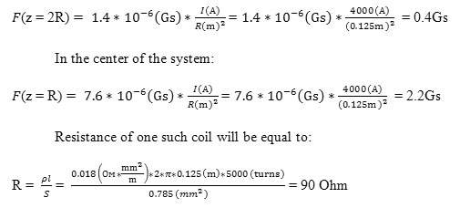
4. Copper wire with 1 mm in diameter. Characteristics:
- Coil cross-section 10sm x 10 sm.
- Inner coil diameter – 20
- Outercoildiameter – 40
- Mid diameter– 30
- Wire diameter– 1
- Wire section= 0.785mm2.
- Number of turns= 100*100 = 10000
Horizontal slice of coil system is presented in Fig. 3.
For the currency density equal to 1А/mm2the voltage will be 0.8А;force at the boarders of the working volume will be equal to:
Current source strength:
P = I2R = (0.8A)2* 2160 hm= 138Wt
Power voltage:
U = IR = 0.8 А* 21260 hm = 173 W
5. Copper wire with 2 mm in diameter. Characteristics:
- Coil 5sm x 10 cm cross-section.
- Inner coil diameter – 20 sm.
- Outer coil diameter – 30 sm.
- Mid diameter – 25 sm.
- Wire diameter – 2 mm.
- Wire section = 3.14 mm2.
- Number of turns= 25*50 = 1250 turns.
Horizontal slice of coil system is presented in Fig. 2.
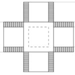 |
Figure 2 |
For the currency density equal to 1А/mm2 the voltage will be 3.14А;force at the boarders of the working volume will be equal to:
Current source strength:
P = I2R = (3.14A)2* 5. 60 hm= 55Wt
Power voltage:
U = IR = 3.14 A* 5.60 hm = 18 W
6. Copper wire with 2 mm in diameter. Characteristics:
- Coil cross-section 10sm x 10 sm.
- Inner coil diameter – 20
- Outercoildiameter – 40
- Mid diameter– 30
- Wire diameter – 2
- Wire section= 3.14 mm2.
- Number of turns= 500*500 = 2500 turns.
Horizontal slice of coil system is presented in Fig 3.
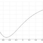 |
Figure 3 |
For the currency density equal to 1А/mm2 the voltage will be 3.15А;force at the boarders of the working volume will be equal to:
Current source strength:
P = I2R = (3.14A)2* 13.5 Ohm= 133 Wt
Power voltage:
U = IR = 3.14 A* 13.5 Ohm = 42 W
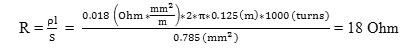
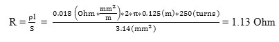
7. Basic variant.
The coil is made of several single coils with air-gap between them for the possibility of airing. (Fig.4).
For a wire with 1 mm in diameter single coil parameters are:
- Wire diameter– 1
- Inner diameter – 20
- Outerdiameter – 30
- Cross-section – 5sm x 2 sm.
- Wire section – 0.785 mm2.
- Number of turns – 1000.
Thus, the resistance of this coil is:
For 10 such coils the power equals:
P = 10 P0 = 720 Wt
This power can be provided by the АКИП-1134-300-5 power sources (Capacity 1.5 kW, Voltage 0-300W, Current 0-5А).
Single coil wire length:
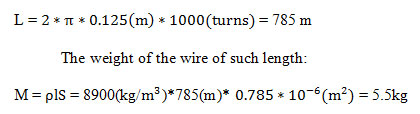
For a wire 2mm in diameter:
Single coil parameters:
- Wire diameter– 2
- Inner diameter – 20
- Outer diameter – 30
- Cross-section – 5sm x 2 sm.
- Wire section – 3.14 mm2.
- Number of turns – 250.
- Resistance of such coil equals:
With current equal to 8А:
P0 = I2R = (8A)2 1.13 Ohm = 72 Wt
For 10 such coils, the capacity is: P= 10 P0 = 720 Wt
Single coil wire length:
L = 2*π* 0.125 (m)* 250 (turns) = 196m
The weight of the wire of such length:
M = plS = 8900 (kg/m3)* 196(m)* 3.14* 10-6(m2)=5.5 kg
Table 1: Gaps and number of turns
| Gap between the turns | Number of turns |
| 1 | 98 |
| 2 | 72 |
| 3 | 55 |
| 4 | 50 |
| 5 | 45 |
Table 2: Gaps and number of turns
| Gap between the turns | Number of turns |
| 1 | 196 |
| 2 | 144 |
| 3 | 110 |
| 4 | 100 |
| 5 | 90 |
Conclusions
According to the above mentioned calculations for sample coil, the following conclusions can be made:
- First, two different geometry for coil cross-section, square one (10 sm on side) andrectangular one (5 sm and 10 sm on sides) produce almost equal forces, which affect dipole (almost 25%), but rectangular section will have better heat characteristics, because it has more surface area-inner volume ratio. Surface area provides cooling and within the inner volume the heating is made.
- Second, the power sources used (АКИП-1134-300-5) help to work with high voltage and with low currents that is why it is more preferable to use copper wire, than copper tube.But the proposed calculation shows that with equal parameters, tubes coils provide more force, means when copper tubes are used the system is more compact.
- The proposed calculations help to choose optimal coil construction for magnetic control system for wireless endoscopic capsule. They can be used for improving technical parameters of the control system in design.
The authors plan to make a sample of the chosen magnet coil and to test it.
Acknowledgement
The publication is prepared in accordance with the scientific research under the Agreement between “Mobile informatics” (LLC) and Ministry of Education and Science of the Russian Federation No. 14.579.21.0053 dated 23.09.2014. Unique project identification number is RFMEFI57914X0053.
References
- Dmitry Mikhaylov, TimurKhabibullin, Igor Zhukov, Andrey Starikovskiy, LandishGubaydulina, Natalya Romanchuk and Vladimir Konev. Development of Retention System of the Autonomous Endoscopic Capsule and Its Functionalities. BIODEVICES 2014. Proceedings of the International Conference on Biomedical Electronics and Devices. ESEO, Angers, Loire Valley, France. 3 – 6 March, 2014. Pages 77-84.
- Sun, Z.-J., Cheng, X.-G., Cao, S., Ye, B., Zhang, H.-H., Liu, S. Multi-applications of a magnet configuration in actuating capsule endoscope. IEEE/ASME International Conference on Advanced Intelligent Mechatronics, 2014. Pages 106-111.
- Gi-Shih Lien, Chih-Wen Liu, Joe-Air Jiang, Cheng-Long Chuang, Yu-Hao Chang, Wen-Chi Huang. Capsule endoscope magnetic control system. Patent application: US 20150087898 A1, publication date Mar 26, 2015.
- Wakefield Glenn. Magnetically propelled capsule endoscopy. Patent application: WO 2004086958 A1, publication date Oct 14, 2004.
- Kim, H.M., Choi, J.S., Cho, J.H. A pilot trial of ambulatory monitoring of gastric motility using a modified magnetic capsule endoscope. Journal of Neurogastroenterology and Motility, Volume 20, Issue 2, 2014, Pages 261-264.
- G.Fluid mechanics, 3 ed., М., 1970.
- SlobodanyukА.I. Physics 10. §12. Permanent magnet field. URL: http://www.physbook.ru/index.php/Слободянюк_А.И._Физика_10/12.7.

