
Abinaya Kumari1, B. Akshaya1, B. Umamaheswari2, K. Thenmozhi1, Rengarajan Amirtharajan1 and Padmapriya Praveenkumar1
1ECE department, SASTRA Deemed University, Thanjavur.
2JECRC, Jaipur.
Corresponding Author E-mail: padmapriya@ece.sastra.edu
DOI : https://dx.doi.org/10.13005/bpj/1446
Abstract
This paper introduces a framework for the secure encryption of healthcare images. The objective of this paper is to encrypt medical images based on Deoxyribo Nucleic Acid (DNA), 3D Lorenz chaotic map, BITXOR operations. The different keys are employed to provide confusion, permutation, encoding and diffusion operations in the encryption procedure to provide uncorrelated image pixels. The proposed algorithm uses 3D Lorenz attractor as chaotic system for encrypting colour Digital Imaging and Communication in Medicine (DICOM) images. Further the encrypted image will be validated using encryption quality to evaluate the security analysis.
Keywords
DICOM; DNA; NPCR; Lorenz Map; UACI
Download this article as:| Copy the following to cite this article: Kumari A, Akshaya B, Umamaheswari B, Thenmozhi K, Amirtharajan R, Praveenkumar P. 3D Lorenz map Governs DNA Rule in Encrypting DICOM Images. Biomed Pharmacol J 2018;11(2). |
| Copy the following to cite this URL: Kumari A, Akshaya B, Umamaheswari B, Thenmozhi K, Amirtharajan R, Praveenkumar P. 3D Lorenz map Governs DNA Rule in Encrypting DICOM Images. Biomed Pharmacol J 2018;11(2). Available from: http://biomedpharmajournal.org/?p=20901 |
Introduction
With the fast advancement in technology and its usage in the field of high speed networks, the security prospective the encryption is essential to keep the health information safe. When transmitted through public channel, this sensitive medical records needs to be secured to prevent damage from attackers. Image encryption plays a key role in protecting those images and hence provides information security in the field of medical imaging. Kanso et al.,1 proposed an algorithm scheme based on traditional encryption scheme with increase in algorithm rounds to encrypt the digital image but these schemes are not appropriate for encrypting the DICOM images owed to their characteristics like, the size of the data is huge, correlation between the pixels is much stronger and redundancy of the data is high. To provide more uncorrelated pixels on encrypted image chaotic map is used for efficient encryption. The main aim of migrating towards the chaos system is, due to its high ergodicity , chaotic system is completely deterministic, its initial seeds are extremely sensitive hence small changes in initial seeds will forever alter the future of chaos system and so on, therefore it has been suggested for encrypting the medical images as considered in.2-5 Because of this characteristics, analysing and predicting the chaos is difficult. Ravichandran et al.,6 discussed that recently DNA computing plays a major role in the domain of cryptography for encrypting the digital images and more random keys are generated using multiple chaotic maps . Li et al.,7 developed an algorithm that uses DNA based computation, it’s advantage are massive parallelism, power consumption is extremely low, capacity for storing the data is large and offers unbreakable cryptosystem. Niyat8 and kalpana9 proposed a scheme with basic idea of encryption based on DNA rule set. In the first stage is to encode the pixels of plain image into DNA sequence. Second stage is to encode using DNA rules like addition, subtraction or XOR operations to form the pixels of encrypted image.
Wang et al.,10 and Enayatifar et al.,11 discussed about DNA encoding rule with algebraic operations like addition operation for encrypting images. Liu et al.,12 proposed an algorithm to yield better entropy for the colour images. Fan et al.,13 uses bit- level permutation and diffusion to boost the protection of the images while ensuring integrity. To ensure the robustness of algorithm, the ideal value of NPCR and UACI is discussed in14,15 Jangid et al.,16 algorithm gives the cryptographic approach using DNA rule set between plain and cipher output. To highly increase the security of encryption and to minimise BER of data an algorithm is proposed by Dang et al.,17
The proposed algorithm has the advantage of achieving good Quality metrics compared with available literature and also the algorithm results shows that the projected algorithm is proficient of resisting a variety of known attacks therefore, appropriate for enhancing security. The content of this paper is discussed as follows; in Section II the related work is discussed. Section III gives the design information of the proposed image encryption algorithm. In Section IV, simulation results are illustrated and in Section V, security features of the algorithm is analyzed. Finally, Section VI is ended with the conclusion part.
Related Work
Lorenz Chaotic System
3D – Lorenz map equations is as follows,
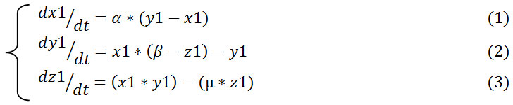
In equations (1),(2) and (3): α , β and µ are the control parameters whereas x1, y1 and z1 are the initial parameters. α, β and µ equals to 10, 28 and 8 /3 respectively and initial values are equal to 1, then 3D Lorenz map is in the chaotic state as in Fig 1a, hence it produces three different chaotic sequences.
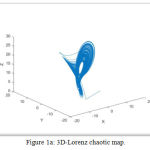 |
Figure 1a: 3D-Lorenz chaotic map.
|
Dna Encoding
DNA encoding is the process of encoding the binary pixel values into sequences. It has four nucleic acid bases such as Adenine (“A”), Cytosine (“C”), Guanine (“G”) and Thymine (“T”). Here, “A” is complement to “T” and “G” is complement to “C” because in 21 binary combination, “0” and “1” are complement to each other and in 22 binary combinations “00” and “11” are complement to each other, “01” and “10” are also complement to each other. In general rule, “A” corresponds to “00”, “C” corresponds to “01”, “G” corresponds to “10” and “T” corresponds to “11” then the coding schemes can be of 24 kinds, still only 8 satisfies the complementary rule as shown in table.1.10 For easy understanding an example is considered, if pixel value is “255” its binary representation is” 11100001” then using general rule this binary value is encoded as “TGAC” each alphabets representing 2-bit respectivel.
Table 1: 8- Sets of Encoding Rules for DNA
| Rule 1 | Rule 2 | Rule 3 | Rule 4 | Rule 5 | Rule 6 | Rule 7 | Rule 8 | |
| 00 | A | A | T | T | C | C | G | G |
| 01
10 11 |
C
G T |
G
C T |
G
C A |
C
G A |
A
T G |
T
A G |
A
T C |
T
A C |
Addition Operation for DNA Sequence
With the rapid development of computations in DNA, the algebraic operations like Addition operation is done. Once the pixels are DNA encoded then addition is done between the DNA encoded data and DNA encoded key sequence as shown in table.2.
Table 2: Addition Rule for DNA
| + | A | T | G | C |
| A | A | T | G | C |
| T | T | C | A | G |
| G | G | A | C | T |
| C | C | G | T | A |
Proposed Image Encryption Algorithm
Section III gives the details of designing the proposed image encryption. The procedure of algorithm includes 4 stages namely confusing, permuting, encoding and diffusing the image in order to enhance the security as in Fig 1b.
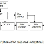 |
Figure 1b: Block description of the proposed Encryption scheme.
|
The encryption steps are described as follows,
Step 1: First, 8-bit RGB DICOM image is used as the plain image IM and it is of size IM(M, N, 3) and S=M*N where M = no. of rows in input image and N = no. of columns in input image i.e. plain image.
Step 2: Split the colour DICOM image IM of size (M, N, 3) into three colour planes as IM_red, IM_green and IM_blue. Separated three colour planes each of size (M,N,1).
IM_ red = {R1, R2, ………, RM*N }
IM_ green = {G1, G2, ………, GM*N }
IM_ blue = {B1, B2, ………, BM*N }
Step 3: Now, three sequences namely X sequence, Y sequence and Z sequence are generated using 3D Lorenz map. s=rows*columns of plain image and generating sequences as follows,
X= {Xi, Xi+1, Xi+2,…………, Xi+(s-1) }
Y= {Yi, Yi+1, Yi+2,…………, Yi+(s-1) }
Z= {Zi, Zi+1, Zi+2,…………., Zi+(s-1) } , where i =1
Now, quantize the X sequence as Key 1 = floor( mod (X*10^14, 256)) and similarly quantize Y and Z to generate other keys i.e. Key2 and Key 3.
Step 4: Sorting the elements of X, Y and Z sequences in ascending order and taking the Index values as Index 1, Index 2 and Index 3 as in Fig 2a and b.
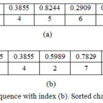 |
Figure 2a: Chaotic sequence with index. (b). Sorted chaotic sequence with index.
|
Step 5: Confusing three colour planes IM_red, IM_green and IM_blue with corresponding Index1, Index2 and Index3.
Step 6: By using the confused image, Permutation is done for three R, G and B planes as follows.1
Let IM = { IM(ii, jj) } denote the grayscale plain image, where ii=1 to M and jj=i to N.
aq(ii, jj) = de2bi (IM(ii, jj)
where function de2bi converts decimal values to binary values.
b = aq(ii , : )
where aq(ii , : ) = {aq(ii , 1), aq(ii , 2),…..,aq(ii , M)} be the ith row of aq, then
c=sum (b)
Taking mod,
Pmod = mod (c, 2).
Now, if Pmod = 0,
a(ii , : ) is circular shifted towards right with Key steps
If Pmod = 1,
a(ii, : ) is circular shifted towards left with same Key steps.
Each group with 8-bits of vector is converted back into binary values, thus permuted image
PRimg = { PRimg(ii, jj) } is obtained as,
PRimg (ii , : ) = bi2de ( a(ii , : )
where ii=1 to M and jj=1 to N.
NOTE: Key1 is used for red plane, Key 2 is used for green plane and Key3 is used for blue plane respectively.
Step 7: BIT- XORing is performed for each R, G and B planes by using permuted image and corresponding key.
q (1) = PRimg (1) ⊕ key (1) (4)
where ⊕ symbol represents Bit-wise XOR operation.
![]()
and
XR (k) = q (k) ⊕ key (k) (6)
where k= {1, 2, 3, 4,………..,S } and S=rows*columns of image.
Step 8: BITXORed image of R, G and B planes and 3 keys are individually encoded using DNA encoding and added using addition rule.
Step 9: Then it is decoded using DNA decoding rule.
Step 10: Finally, Diffusion is performed for each RGB planes to get cipher image as in Fig 3.
Each RGB planes is first bitxored with Key 1 [row-wise],
Pdif = { Pdif (ii, jj) } , where ii=1 to M and jj=1 to N (7)
and
Pdif (ii , : ) =DNAout (ii , : ) ⊕ key1 (ii , : ) (8)
Now, bitxoring the results of first stage with another key i.e Key2 [column-wise] is written as,
Pdif (: , jj) =Pdif (: , jj) ⊕ key2 (: , jj) (9)
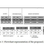 |
Figure 3: Flowchart representation of the proposed algorithm.
|
Simulation Results And Security Analysis
For experimental analysis, 3 colour DICOM images were considered. Encryption metrics like NPCR, UACI, and correlation were estimated to prove the strength of the proposed encryption scheme. Fig 4(a-e) and 5(a-e) shows the various stages output of the proposed algorithm. The proposed encryption algorithm is said to be superior, if it is indestructible in any cases and it should resist towards common attacks as discussed in this section and also this section demonstrates a security analysis on proposed encryption scheme.
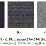 |
Figure 4: Encryption Results(a). Plain image(256×256) (b). Confused image (c). Permuted image (d). Bitxored image (e). Diffused image(Encrypted image).
|
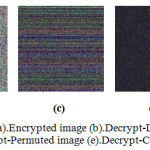 |
Figure 5: Decryption Results (a). Encrypted image (b). Decrypt-Diffused image (c). Decrypt-Bitxored image (d). Decrypt-Permuted image (e). Decrypt-Confused image.
|
Statistical Attack Analysis
It can be estimated by analyzing the pixels in the encrypted histogram, global entropy and correlation coefficients of encrypted image.
Entropy Analysis
The Shannon entropy is adopted, in this case the randomness of random variable XX is measured as follows,
![]()
where each is the possible value of . For M=8-bit data and q levels [q=2M], the range of entropy will lies in range [0,M]. If the entropy is little in the input data then the resultant key will have higher entropy. In general, entropy of the encrypted image should have value close to M, else if entropy value is lesser then there is a possibility of attack which can reduce the security of image transmission. Table. 3 shows that all the values of each RGB planes for 3 test images are more closer to M and hence algorithm which is proposed is much efficient.
Table 3: Entropy Analysis of 3 Test Images
%0


This work is licensed under a Creative Commons Attribution 4.0 International License.
| Images | Plain Image | Cipher Images | |
| Image 1 | R |