Sunil Chandy Varghese1, S. Kishore Kumar2
1Sr. Lecturer, Dept. Of Orthodontics,Tagore Dental College and Hospital, Chennai, India. 2Professor, Department of Orthodontics, Sree Balaji Dental College and Hospital, Bharath University, Pallikaranai, Chennai-600100
DOI : https://dx.doi.org/10.13005/bpj/693
Keywords
3d; Imaging; Implications; Orthodontics; review
Download this article as:| Copy the following to cite this article: Varghese S. C, Kumar S. K. 3d Imaging and its Implications in Orthodontics.- A review. Biomed Pharmacol J 2015;8(October Spl Edition) |
| Copy the following to cite this URL: Varghese S. C, Kumar S. K. 3d Imaging and its Implications in Orthodontics.- A review. Biomed Pharmacol J 2015;8(October Spl Edition). Available from: http://biomedpharmajournal.org/?p=3477> |
Treatment planning with 3D imaging will evaluate more factors than linear measurements, angles, goals of occlusion and facial esthetics. The 3D imaging can be useful in evaluating treatment responses to functional orthopedics, orthognathic surgery and growth of the face.
Limitation Of 2d
Several reasons for limited validity of the 2D Cephalometry’s scientific method :
- A conventional headfilm is a 2D representation of a 3D object.
- Cephalometric analyses are based on the assumption of a perfect superimposition of the right and left sides about the mid sagittal plane
- A significant amount of external error, known as radiographic projection error, is associated with image acquisition.
- Size
- Magnification
- Distortion
- Patient positioning
- Projection distortion
- Manual data collection and processing in cephalometric analysis has been shown to have low accuracy and precision.
- Errors in location of landmarks due to the lack of well defined outlines, hard edges and shadows.
3D Imaging
Selected digital imaging devices can produce digital volumes or 3D images. The volume element (voxel) is the smallest element of a 3‑dimensional image. A voxel volume can be thought of as a 3D array or stack of bitmapped images, with each voxel having height, width, and thickness.
Why Do We Need A Three Dimensional Record???
In clinical orthodontics it is not enough just to accurately image the facial shape but essential to be able to detect changes in the image. When evaluating the success of appliance therapy it is also important to be able to distinguish between changes in morphology due to treatment and changes due to other factors such as growth and normal variation.
Basic Principles to Measure in Three Dimensions
There are two geometric strategies for measuring in three dimensions. They are
– Orthogonal Measurement
– Measurement By Triangulation
Systems that measure by triangulation analogize the geometry of mammalian stereoscopic vision. Typically such systems view the object to be measured from two positions in space and capture images from both positions on film or some digital medium either simultaneously or in rapid succession.
Both biplanar and coplanar stereo systems are examples of triangulation geometry.
All the 3D measuring systems must be able to identify the same anatomical structure in all three dimensions.
To meet this obvious requirement frequently it is not as easy as it sounds, especially in stereoscopic X-ray systems.
The greater the separation between the X-ray sources for two of the images of any stereo pair, the more difficult is to identify the same landmark in both images.
When other factors are equal, the most powerful geometric solution for any stereoscopic measurement occurs when the angle between the two emitters and the object being imaged approximately 90 degrees.
However most skull structures of orthodontic interest look very different, when viewed from the lateral and frontal projections. Hence the trade off between coplanar and biplanar methods.
In effect, the coplanar method sacrifices some of the mathematical power of the 90- degree ray intersection of the biplanar system to obtain a pair of images on which it is possible to locate the same physical point on both images with reduced error.
Methods of 3d Facial Imaging:
- Laser Scanners
- Structured Light Patterns
Methods of Three Dimensional Cranio Facial Skeletal Imaging:
- Computed Tomography
- Newtom
Methods of 3d Intra Oral Dental Imaging:
- Intra Oral 3d Camera
Methods of Capturing Mandibular Motion in 3d:
- Ultra Sonic Motion Capture
Applications of 3d Imaging in Orthodontics Digital Study Models:
The digital study models overcome most of the problems (drawbacks) of plaster study models in addition to being the last component of a fully electronic patient chart (with digital photography and digital radiography already in use).
This computerized system opens a new realm of orthodontic diagnosis.
Procedure
There are two basic methods of producing digital study models:
Destructive imaging: Removes part of a cast, little at a time, while it is being imaged.
Non destructive imaging: uses structured light, laser light, or x-ray to image while leaving the original cast intact.
Two major successful companies in producing high quality 3-D models:
- Orthocad
- Geodigm
Recent technologic advances now allow the models to be digitized, measured with software tools, stored electronically, and retrieved with a computer. OrthoCAD (Cadent, Fairview, NJ) performs this service.
Advantages of Digital study models
- Elimination of model breakage
- Eliminates storage problems
- Instant retrieval of models
- Ease of communication with patients and colleagues
- Model access from many locations.
- Enables the orthodontist to e-mail images
- Convenient presentation tool
Disadvantages of digital study models
- Lack of tactile input for the orthodontist
- Virtual models cannot be mounted and articulated in reference to patients TMJ functions, although jaw alignment tool comes close to this.
- Time needed to learn how to use the system.
OrthoCAD
(Cadent, Fairview, NJ) is a patented computer model system that creates digital images of dental casts. To obtain the digital images, the orthodontist sends alginate impressions and a wax bite to the OrthoCAD laboratory.
The impressions are scanned, converted into digital images that are stored on the company’s server, and made available for downloading by the account holder. OrthoCAD provides software the orthodontist can use to make routine measurements, such as tooth size, overjet, overbite, and Bolton analysis, on the digital images.
Geodigm
Geodigm e-models are constructed through a proprietary laser scanning process that digitally maps geometry of patient’s anatomy into a high dimensional 3-D image, with an accuracy of 0.1 mm. Scanners project a laser stripe on surface of cast and use digital cameras to analyze distortions in stripe. The cast is oriented in all axes to expose for scanning. This produces 3D vertices that are connected into thousands of triangles to form the 3D image. The software then displays the e-model on the computer screen by giving colour shades to each triangle based on its orientation to digital light source.
Clinic management of models:
The orthodontist sends the impressions and bite registration to Geodigm and plaster cast is made which is scanned to an e model and articulated. The model can be then downloaded from main server. A copy is maintained on Geodigm server for security of data storage.
Using models, clinician can move, rotate, or zoom in any plane or orientation. Point to point, Bolton analysis, and curve length measurement can easily be made by pointing and clicking mouse.
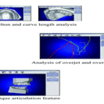 |
Figure 1 |
Colour bite mapping features permit analysis of occlusal relationships, 3D colour coded map demonstrates occlussal content between arches. In addition, there is an articulation feature which allows clinician to set centre of rotation.
One of the latest developments is e plan, which simulates multiple treatment plans to help determine most effective treatment. This also allows simulation of rotation movements and allows patient to view their own teeth from malocclusion to a post treatment view.
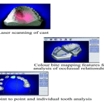 |
Figure 2 |
Holography
Holography is the name given to the process of wave front reconstruction and comes from the Greek words ‘holos’, meaning whole and ‘gramma’ meaning message.
A hologram is a photographic film, slide or plate upon which is recorded the interference pattern produced by the reinforcement or cancellation of 2 different intersecting light wave fronts. Holography is the science of recording the reflected light waves from an object on to a hologram and subsequently reconstructing the stored image of the object in the space where the original object had been. The recorded image is called a hologram.
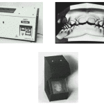 |
Figure 3: Holograms |
Advantages of holograms
Schwaninger et al (1977) proposed potential advantages of holograms as a substitute for study casts.
- Holograms are very resistant to damage.
- Better suited to transport by post.
- Can be stored with patient’s clinical records.
- Accurate measurements such as intercanine width can be measured.
Disadvantages of holograms
- Once made a hologram cannot be adjusted like a set of study casts.
JT-3D
- JT-3D precisely measures even the smallest movements of the mandible.
Its state-of-the-art design makes no contact with the patient’s face to provide a claustrophobic-free experience.
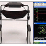 |
Figure 4 |
3d Cephalometry
In traditional cephalometry 3D craniofacial structures are projected onto 2D radiographic film. This process creates cephalometric landmarks that do not exist in patient. These structures are effectively optical illusions of craniofacial anatomy.
Examples are mandibular symphysis, pterygoid fossa, and the key ridge.
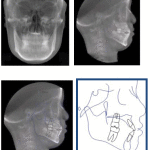 |
Figure 5 |
CT imaging
Since the 1980s, the quality and speed of CT imaging has changed dramatically.
Now with improved techniques and imaging programs it is possible to produce images, which can be rotated and cut at any level.
Conebeam Computed Tomography (CBCT)
Conebeam CT (CBCT), also known as Conebeam Volumetric Tomography (CBVT), produces accurate 3D image data of the craniofacial region, with low radiation dose. Conebeam CT is a new form of computed tomography which uses different source detectors and a different type of acquisition than traditional Fan-beam medical CT.
The radiation dosage of conventional CT is much higher than Conebeam tomography
Conebeam volumetric tomography uses one rotational sweep of 360 degrees. The scan times vary between 5 to 75 seconds, depending on the field of view and the CBCT unit used. One of the biggest advantages of Conebeam CT, is that the doctor can get much more accurate information from one Conebeam scan than the multiple 2D views, we traditionally use, with much less radiation.
Spiral Ct
Recently, a new CT technique, spiral CT (SCT or volume acquisition CT), has been developed. This method has several advantages over standard CT imaging.
- By employing simultaneous patient translation through the x-ray source with continuous rotation of the source-detector assembly, SCT acquires raw projection data with a spiral sampling locus in a relatively short period.
- Without any additional scanning time, these data can be viewed as conventional trans axial images, as multiplanar reconstructions, or as three-dimensional (3D) reconstructions. Such images provide an opportunity to obtain accurate images at any arbitrary location within the volume data set.
- The unique arrangement of the gantry and rotating x-ray source assembly radically reduces scan times.
- Partial body scans can be completed during a single breath hold. With standard incremental CT, small objects can be missed or their detection compromised if the patient’s degree of inspiration and expiration varies from scan to scan.
- Moreover, multi planar and 3D image reconstructions of structures from standard incremental CT data are degraded by motion-induced mis-registration artifacts
New Tom Scanner
The NewTom 900 scanner uses a cone‑shaped x‑ray beam that is large enough to encompass the region of interest. This type of beam uses the x‑ray emissions very efficiently, thus reducing the absorbed dose to the patient. This type of beam also allows for the acquisition of the image data in 1 revolution of the x‑ray source and detector without the need for patient movement.
These attributes make this system more efficient and mechanically simpler than others, and thus it can be designed for specific purposes, such as imaging the maxillofacial region.
The NewTom 9000 volume imaging technique uses the principle of Tomo synthesis or cone‑beamed CT because of the shape of the x‑ray beam
In a single scan, the x‑ray source and a reciprocating x‑ray sensor rotate around the patient’s head and acquire 360 pictures (1 image per degree of rotation) in 17 seconds of accumulated exposure time. The entire maxillofacial volume (13‑cm‑diameter field of view) is enraged, and the patient receives an absorbed dose similar to a periapical survey of the dentition.
The 360 acquired images undergo a primary reconstruction to mathematically
replicate the patient’s anatomy into a single 3D volume that comprises voxels similar to those of a Rubik’s cube. Each voxel is small
(0.29 mm for each of the cube faces), thus the image has a relatively high resolution.
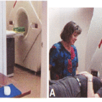 |
Figure 6 |
The New Tom 9000 Volume scan has been extremely valuable for investigating impacted teeth, temporo mandibular joints, implant planning, and pathology.
Three-dimensional scans can give valuable information about areas of the dentition, such as the position of the maxillary incisor roots relative to the lingual cortical border of the palate to plan retraction, the amount of bone in the posterior maxilla available for distalization, the amount of bone lateral to the maxillary buccal segments available for dental rather than skeletal expansion, airway information on the pharynx and nasal passages, maxillary root proximity to the maxillary sinus, and the position of the mandibular incisor roots in bone.
These scans also allow 3D visualization of bony defects and supernumerary teeth in patients with cleft lips or palates.
Axially corrected tomograms of the temporo mandibular joints can be obtained from the same scan.
MRI
MRI is good for 3D imaging of soft tissues but the accuracy of the data is not sufficient for precision milling of prostheses, as it does not differentiate between air and bone. However, for soft tissues it is excellent, and can be useful in imaging temporomandibular joints.
It is also useful in the management of tumors of the head and neck region and for imaging the brain for neurological problems.
Optical Surface Scanning
Optical surface scanning was first tested in 1981 to produce a non-invasive 3D image of the face. It is important to have sufficient data over all the surfaces for the analysis of changes in facial morphology, and especially of surface shape changes
In forensic science, optical surface scanning has proved valuable in assisting in identification by building faces over dry skulls that have been found
Stereophotogrammetry
Stereophotogrammetry has evolved from old photogrammetric techniques to provide a more comprehensive and accurate evaluation of the captured subject. This technique uses one or more converging pairs of views to build up a 3D model that can be viewed from any perspective and measured from any direction. The earliest clinical use of stereophotogrammetry was reported by Thalmann – Degan in 1944 who recorded change in facial morphology produced by orthodontic treatment.
The 3d Md Stereo Photogrammetric Scanner
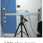 |
Figure 7 |
It consists of an array of digital cameras used to perform surface imaging of the patient’s face.
A quick scan will generate a clinically accurate three-dimensional digital model of the patient’s face.
Rapid Prototyping
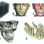 |
Figure 8: Rapid Prototyping |
Dental models made with rapid prototyping could become the diagnostic procedure of choice for evaluating impacted maxillary canines.
Use of a Rapid Prototyping
The use of a rapid prototyping dental model seems to provide significant advantages in the diagnosis, treatment planning, and communication with patients for impacted maxillary canines when compared with conventional radiography and CT scans .
Prototyping can become a new tool in the production of brackets and other precision apparatuses for specific cases.
3d Morphometry
Three-dimensional (3D) imaging has evolved greatly in the last two decades and has found applications in orthodontics, as well as in oral and maxillofacial surgery. In 3D medical imaging, a set of anatomical data is collected using diagnostic imaging equipment, processed by a computer and then displayed on a 2D monitor to give the illusion of depth.
Depth perception causes the image to appear in 3D.
Facial Image Acquisition
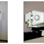 |
Figure 9:Facial Image Acquisition |
A standard stereo camera set-up is used to capture the facial image pairs. The two cameras are attached to a specially designed stereo base which sits on a tripod. Each camera can translate and rotate along this base so that the convergence angle, baseline separation and height are adjustable. Digitally controlled slide projectors are used to flash separate random texture and structured light patterns onto the subject’s face.
- The CCD cameras used have a resolution of 768 x 576 pixels and these are digitized in a frame grabber able to store up to sixteen 8 bit grey level images in RAM. The cameras are pre-calibrated using precisely defined circular control point targets.
- Random texture is used to aid the search for point correspondences in the matching phase. Without this large areas of the face are relatively featureless and stereo-correlation produces many false matches.
- Image pairs acquired using texture (IL, IR) and structured light (SL, SR) projection are taken. Using digitally controlled switching between cameras and projectors, the time between capture is less than one second. Any slight subject movement is unimportant since the structured light pair is used only at the image partitioning stage.
- Clearly, it is not possible to capture the entire face with only one stereo pair. An additional stereo pair for the left and right sides of the face, is required followed by a step to register the three facial models.
How is 3d Information About the Surface of the Face Obtained?
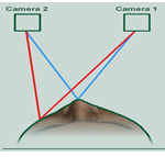 |
Figure 10 |
Ranging the location of two representative points on the face from a pair of cameras located a known distance apart.
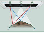 |
Figure 11 |
A known pattern is projected upon the subject from a light source (A) and photographed by a digital camera (B)
In a more recent development, a second digital camera (C), mounted between the fixed projector (A) and digital camera (B) captures a true-color image a few milliseconds after the primary image.
The 3D information from the primary-camera-light-projector assembly is synchronized with the 2D pixel map from Camera C and is stored in a kind of look-up table.
In this way, the location of each pixel on the monitor-displayed image from Camera C uniquely identifies the three dimensional coordinates of a particular point on the surface map generated by Camera B and its associated projector (A). A dedicated computer chip built into the digital camera has the ability to distinguish different frequencies of light and hence can tell, from the color of each light ray, the direction in which that particular ray has traveled from the light projector.
The projected pattern falling upon the subject is photographed by Camera 1 which is mounted a known distance from the Projector. When viewed from the perspective of the Projector, the shape of the projected pattern remains unaltered regardless of the shape of the object it falls upon.
The reconstructed representation of the face can be rotated on a standard computer monitor and the 3D coordinates of any visible point can be captured by pointing and clicking with a standard mouse or other similar device The system is capable of generating dense 3-D surface maps by an image partitioning strategy and stereo matching phase,
The accuracy of Euclidean reconstruction has been established by analyzing images of a plaster cast model of a human face containing 13 simulated facial landmarks.
This model was placed at nine different orientations and locations within the calibration space. Stereo image pairs were captured at each pose and the corresponding landmark features were detected using a centroid detection algorithm.
These landmark points were then reconstructed to produce nine independent 3-D point sets. The point sets were then registered to a common coordinate frame using a standard approach, and the mean landmark positions determined.
Automatic 3-D Landmark Extraction
The method developed for automatic facial shape change analysis is a combination of stereo-assisted feature detection and morphometric techniques. One advantage of using a stereo-based image acquisition system is that the surface texture is captured which facilitates robust 3D landmark extraction. Coupled with this, the use of morphometric techniques provides a geometrically and statistically meaningful way to characterize the shape change.
Active Shape Model
An active shape model (ASM) is a statistically-based technique for building geometric models of the shape and grey level appearance of a variable object in order to automatically locate new instances of the object in 2D images. It has been used successfully to locate the main facial features in images obtained under widely varying conditions .
This technique is now extended to 3-D facial landmark extraction by using stereo correspondence search and surface map interpolation.
Conclusion
The applications of 3D imaging in orthodontics include pre- and post-orthodontic assessment of dentoskeletal relationships and facial aesthetics, auditing orthodontic outcomes with regard to soft and hard tissues, 3D treatment planning, and 3D soft and hard tissue prediction (simulation).
Three-dimensionally fabricated custom-made archwires, archiving 3D facial, skeletal and dental records for in-treatment planning, research and medico-legal purposes are also among the benefits of using 3D models in orthodontics
Review of literature
- Current Products and Practices Applications of 3D imaging in orthodontics: Part I Journal of Orthodontics, Vol. 31, 2004, 62–70, M. Y. Hajeer.
- The Use Of Three-Dimensional Imaging In Orthodontics* The European Journal of Orthodontics 2006 28(5):416-425; JP Moss.
- To evaluate the reliability of the OrthoCAD system.(AJODO 2003;124:101-5);Scott
- Comparison of measurements made on digital and plaster models .AJODO2003 Jul;124(1):101-5.; Santoro M.
- Holography in dentistry October 1997 Volume 95, Issue 4, Pages 814–817, Bernhard Schwaninger


