
Manuscript accepted on :22-08-2025
Published online on: 16-09-2025
Plagiarism Check: Yes
Reviewed by: Dr. Elina Margarida Ribeiro Marinho
Second Review by: Dr. Noor-Al Huda A. Yahya
Final Approval by: Dr. Anton R Keslav
Aashish Joshi1,2* , Kailash Karande2and Ravindra Gunaki3
1Department of Electronics and Telecommunication Engineering, S.K.N Sinhgad College of Engineering, Korti, Pandharpur, Dist Solapur, Maharashtra India 2Department of Electronics and Telecommunication Engineering, Fabtech Technical Campus College of Engineering and Research, Sangola, Dist Solapur, Maharashtra, India 3Orthopaedics Department, KVV Krishna Institute of Medical Sciences, Deemed University (Krishna Vishwa Vidyapeeth) Karad, Satara, Maharashtra, India. Corresponding Author E-mail:ashu.joshi05@gmail.com
DOI : https://dx.doi.org/10.13005/bpj/3254
Abstract
This study investigates the application of DHS (Dynamic Hip Screw) stabilization in elderly patients with proximal femur fractures. To ensure clinical fidelity, consultations with orthopedic surgeons were conducted before simulating DHS screw insertion. The primary focus was to analyze the stress distribution patterns in the bone, implant, and interface area under various loading conditions, a critical factor for older patients with stable fractures for whom DHS stabilization is considered optimal. Finite Element Analysis (FEA) was utilized to assess the mechanical behavior of the implant and femur under simulated conditions. The parameters were selected based on the literature available like Von-Misses stress, Concept of Factor of safety. The life cycle parameters like load cycle, allowable range of fatigue and extreme values of the fatigue are also taken care. Since these impact outcome of the simulation. Domain expertise has been received which has helped us deeper understanding and better visualization. To ensure simulation model is adequately calibrated and validated. Subsequently, fatigue analysis for high-cycle loading conditions was conducted, incorporating Factor Of Safety (FoS) computations for both the implant and the post-operative femur bone. The results indicated that the FoS ranged from 1 to 15, with the mid-femur displaying the minimum FoS value of 5, and the proximal femur showing the maximum FoS. This suggests a significant increase in the overall FoS following the virtual operation, demonstrating enhanced stability and structural integrity of the femur post-DHS stabilization. These findings underscore the effectiveness of DHS stabilization in improving load distribution and reducing the risk of further complications in elderly patients with proximal femur fractures. This simulation procedure has been validated with help of expert orthopedic surgeons to perform exact simulations as per the medical practice requirements such validation letters are also obtained as proof for the research work.
Keywords
Fatigue Analysis; Fracture; Proximal Femur Bone; Stress; DHS Screw; Factor of Safety (FoS); Finite Element Analysis (FEA); Operative planning; Surgical simulation
Download this article as:| Copy the following to cite this article: Joshi A, Karande K, Gunaki R. Finite Element Analysis of Proximal Femur Fractures: Evaluating Fatigue Performance and Factor of Safety of DHS Screw Fixation. Biomed Pharmacol J 2025;18(3). |
| Copy the following to cite this URL: Joshi A, Karande K, Gunaki R. Finite Element Analysis of Proximal Femur Fractures: Evaluating Fatigue Performance and Factor of Safety of DHS Screw Fixation. Biomed Pharmacol J 2025;18(3). Available from: https://bit.ly/3Ij3xZw |
Introduction
As medical technology advances and redefines the landscape of orthopedic surgery, the integration of computational tools and biomechanical analyses has emerged as a critical component in refining surgical methodologies.1 In this context, the creation of a Fatigue Analysis-Based Femur Bone Virtual Operation Evaluation Method represents a significant step towards improving preoperative planning and postoperative outcomes.
The femur, as a vital weight-bearing bone, is prone to fracture, especially in situations involving fatigue loading.2 Traditional methods of evaluating surgical procedures frequently fail to predict their long-term effects. As a result, a paradigm shift towards incorporating fatigue analysis into the virtual operation assessment is required for a complete understanding of the dynamic interactions between the implanted hardware and the biological structure.
This novel approach uses FEA to simulate the mechanical responses of the femur under various stress conditions. Including fatigue considerations in the virtual operation evaluation provides orthopedic surgeons with valuable insights into the potential durability and performance of the surgical intervention over time. This not only helps to optimize implant selection and placement, but it also provides a proactive approach to reducing postoperative complications caused by fatigue-induced failures.
This paper describes the conceptual framework, methodology, and potential clinical implications of the Fatigue Analysis-Based Femur Bone Virtual Operation Evaluation Method, emphasizing its importance in improving the precision and efficacy of orthopedic surgical planning.3 Here Fatigue Analysis-Based Femur Bone Virtual Operation Evaluation Method refers to simulating a femur bone virtual operation to find out bone strength. In very normal terminology it refer to preparing 3D model by using computer to analyze how the bone will behave under various stress condition here referred as loading conditions after a virtual surgery by using an implant . The reason to work with this is after a virtual operation how to determine the stability and reliability of femur-implant operated structure so that surgeon can suggest post-operative movements to the patients. The fatigue has been analyzed in the context of femur bone only. Femur bone fatigue is complex process that’s why we have tried to simplify by using the variables like loading frequency, extreme values of fatigue and mathematical calculations for the samples has been analyzed and interpreted for better clarity. Bone mechanics has been included to simplify bone fatigue.
Predicting the bone-implant assembly’s long-term performance and endurance under cyclic loading circumstances requires fatigue study. Use a load type that is representative of normal physiological loading conditions for this situation. In this analysis, a fully reversed load is taken into account. In order to replicate long-term use, medical implants typically undergo high-cycle fatigue studies. The direction of the load amplitude, which is set based on the peak load from the static analysis (600 N). Enter the materials’ fatigue characteristics (bone and implant). Among these is the stress-life data, or S-N curve, which describes how the material reacts to cyclic loads.as shown in Figure 1. Equation 1 indicates how factor of safety is calculated.
![]()
For example: If a femur’s maximum allowable stress (failure strain level) is 180 N/mm² and the peak functional strain is 30 N/mm², the safety factor would be 180/30 = 6.
 |
Figure 1: S-N curve showing the low-cycle and high-cycle regions.Click here to view Figure |
Stress Vs Number of Cycles in the log scale
The integration of computational tools and biomechanical analyses has transformed orthopedic surgery, particularly in the context of femur bone interventions. One area of significant interest and innovation is the use of Fatigue Analysis combined with Factor of Safety calculations in virtual operations, which provides a more nuanced understanding of the biomechanical aspects and long-term performance of surgical interventions.4,5
Review of Virtual assessment by Fatigue Analysis / Factor of Safety
Comprehending fatigue behavior and maintaining the safety of femoral bone structures are critical in orthopedic biomechanics. Current study has focused on advanced methods for experimentation, computational modelling approaches, and clinical implications for analyzing properties of fatigue and effectively applying factors of Safety.
The studies continue to shed light on the fatigue behavior of the femur bone. Li et al. used high-resolution imaging techniques to investigate how loading frequency and stress amplitude affect fatigue life.6 Their findings emphasized the significance of microstructural features in regulating fatigue crack initiation and propagation within the femur, but author has failed to explain the stability of femur bone under significant loading conditions.
Technological advancements have helped to improve the experimental characterization of femur fatigue properties. Liu et al. used DIC (digital image correlation) and in-situ loading to investigate strain distributions and micro damage accumulation in femoral specimens under cyclic loading conditions.7 Their findings offer important insights into localized fatigue mechanisms. The author has failed to study stability even micro damage has been taken in to consideration.
Materials and Methods
To estimate the success of the operation, FOS calculations were applied to the femur bone fracture model following the virtual operation on patients. A comprehensive software setup, incorporating virtual operation and fatigue analysis, was employed on a sampled dataset. The 3D models were developed from a DICOM Dataset obtained from CT scans. The DICOM format of CT scan data consists of two-dimensional human greyscale images. The 3D models were imported into ANSYS for material assignment and further analysis.8,9 This process allowed for detailed evaluation of the structural integrity and durability of the femur post-operation, providing crucial insights into the effectiveness of the surgical intervention as shown in Figure 2.
Following Table 1 indicate the material used for femur and implant used including biomechanical characteristics as the implant has been designed in CAD but recommended material for DHS screw as implant is 316L stainless steel or titanium alloy which is typically used medical implants.
FEA – Fatigue Analysis of Femur Healthy Bone vs. Cracked Bone:
Understanding the stress distribution pattern in the bone, implant, and interface region under real-time loading conditions is crucial when the implant is subjected to varying loads. FEA (Finite Element Analysis) was conducted in ANSYS Workbench (R16) to simulate different physical activities. During walking cycles, variable loads are experienced, with the load peaking when the foot touches the ground and reducing to zero when it is lifted.
 |
Figure 2: Workflow for Fatigue AnalysisClick here to view Figure |
Table 1: Mechanical Properties of the Implant and Bone under study[10,11]
| Sr. No. | Parameter used | Values of the Parameter |
| 1 | Crack Length ( Fracture Line) | 0.5 mm |
| 2 | Load Applied on Proximal Part | 600N |
| 3 | Density of the Bone | 2000 kg/m3 |
| 4 | Density of Implant | 7850 kg/m3 |
| 5 | Young’s Modulus of Implant | 2.0E+05 MPa |
| 6 | Young’s Modulus of Sample Bone | 2130 MPa |
| 7 | Poisson Ratio Of Implant | 0.3 |
| 8 | Poisson Ratio Of Sample Bone | 0.3 |
The following steps outline the FEA process:
Import Geometry: Load the 3D model of the femur and implant into the ANSYS Workbench environment.
Material Model: Assign appropriate material properties to the bone and implant components.
Contact Definition: Define the contact interactions between the bone and implant surfaces.
Discretization: Generate a finite element mesh to discretize the geometry for analysis.
Apply Boundary Conditions: Set boundary conditions and apply the variable loads corresponding to walking cycles. The data used are taken from literature for the loading cycles.
Results and Post-Processing: Analyze the results to understand the stress distribution and evaluate the performance of the implant and bone under the specified loading conditions.
This methodology ensures a comprehensive analysis of the mechanical behavior of the femur and implant, providing valuable insights into their performance during typical physical activities. The crack here considered are stable (simple) types of fractures where fracture geometry was major focus.
Import geometry in ANSYS Workbench environment
The assembly model created in CATIA was saved in the .stp file format, compatible with ANSYS Workbench, which accepts IGES, STEP, and Parasolid file formats. The figure below illustrates the bone-implant assembly within the ANSYS Workbench environment. For this analysis, the bone is assumed to be a linear isotropic material meaning its mechanical properties are identical in all directions. The details are summarized in Table 1. 10, 11,21
Contact definition
In this study, a bonded type of contact is applied at the bone-implant interface. Since parts are rigidly joined hence it forms a critical parameter in simulation perspectives at last it has worked as s single unit. As result it has been mentioned as bone-implant assembly. This ensures that there is no relative motion between the two surfaces, which ensures continuity of the model allowing forces to transfer between gaps also. Hence in simulations accuracy of the virtual operation has been improved. Note that relative motion between parts is no more4 useful. Accurately simulating the intended mechanical behavior of the assembly. We have included bonded type of contact. Before proceeding with the finite element analysis, it is crucial to verify that all contacts are in a closed status. The details are shown in Figure 3A and Figure 3B. 21Open contacts can significantly affect the accuracy of the solution by introducing unrealistic gaps or slip between the bone and implant.
Steps for Defining and Verifying Contact in ANSYS Workbench
Define Contact Type
Set the contact type as “bonded” at the bone-implant interface. This configuration restricts relative motion, ensuring that the bone and implant act as a single unit under load. Bonded type of contact have zero degree of freedom, avoiding sliding or slippery hence fatigue analysis becomes easy for the simulations.
Contact Verification
Before running the analysis, check the status of all contacts to ensure they are closed. This involves reviewing the contact pairs and their statuses in the ANSYS Workbench interface.
Simulation Integrity
Ensuring closed contacts is essential for the integrity of the simulation. Open contacts can lead to erroneous results by failing to accurately represent the mechanical interlocking between the bone and implant.
Discretization – finite element mesh
In the discretization process, the infinite degrees of freedom problem is converted into a finite degrees of freedom problem. This is achieved by dividing the geometry into a finite number of elements. The number and type of elements significantly influence the accuracy and output of the model.11 For this analysis, quadratic tetrahedron elements are chosen for finite element mesh generation due to their ability to provide more accurate results in complex geometries. The 3D geometry of the bone-implant assembly is divided into a finite number of smaller elements.13,15 This process is known as meshing.
Element types
Quadratic tetrahedron elements are selected for the mesh.14 These elements are preferred because they offer higher-order interpolation and better accuracy for representing curved surfaces and complex geometries compared to linear elements.
Body element- SOLID187
3-demensional 10 node tetrahedral element.
Quadratic Displacement Behavior.
Suited for irregular geometry
Contact element – CONTA174.
3-demensional 8 node surface to surface contact element.
3 DOF at each node- Translation in X, Y and Z direction.
Element located on surface of 3D solid.
Figure 4 shows SOLID187 and CONTA174 elements. Bonded contact, particularly after Osseo integration, when bone growth forms a tight connection, is utilized to represent the strong, direct engagement between the bone and implant in virtual surgical planning for femur bone and implant interactions. In virtual surgeries, this aids in precisely simulating load transfer, stress distribution, and the mechanical stability of the implant-bone contact.22 Bonded type of contact commonly used as it simplifies the simulations , make it computationally easier and faster for the analysis purpose.
SOLID187 is a high-order element used in finite element analysis (FEA) simulations, which means it uses more nodes per element and more complex interpolation functions, which allows it to capture the shape of curved surfaces with greater accuracy than lower-order elements. SOLID187 is frequently chosen for modelling curved surfaces and complex geometries, making it a suitable choice for bone-implant models.
C Loads and Boundary Conditions
In this finite element analysis, boundary conditions and loading are crucial for simulating the real-life behavior of the bone-implant assembly. Here, the bone is constrained (fixed support) at the bottom end, and a vertical load of 600 N is applied to simulate typical loading conditions. This load represents the force exerted by a 60 kg person and is directed downwards to simulate weight-bearing conditions. 10-11, 16
This constraint ensures that there is no displacement or rotation at the fixed end, effectively simulating the support provided by the rest of the body. It means that during the work we have focused on the proximal part of the femur (Femoral Head) ,in case of simulations and forces to applied. In the “Static Structural” module, apply the load to the relevant loading point or area on the bone-implant assembly. It ensures the load is correctly oriented in the vertical direction to accurately mimic physiological loading conditions.17-20.The static structural analysis is favored in simulations where you need to analyze how structure (Femur bone- Implant Assembly) under steady and static load which leads to good approximations during virtual operation, allowing it to predict stress with in various parts of the femur bone which helps in surgical planning.
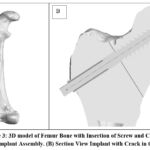 |
Figure 3 3D model of Femur Bone with Insertion of Screw and Crack .Click here to view Figure |
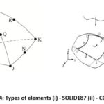 |
Figure 4: Types of elements (i) – SOLID187 (ii) – CONTA174Click here to view Figure |
Fatigue Analysis Set Up
Fatigue analysis is essential for predicting the long-term durability and performance of the bone-implant assembly under cyclic loading conditions. For this scenario, use a load type that represents typical physiological loading conditions. A fully reversed load is considered in this analysis. A fully reversed load means loads alternates between tension and compression over each loading cycles. High-cycle fatigue analysis is generally used for medical implants to simulate long-term use since daily activities of the subject to repetitive and relatively low magnitude of loading cycles. Load amplitude is set based on the peak load from the static analysis (600 N), the direction is as indicated in Figure 5. Input the fatigue properties for the materials used (bone and implant). This includes the S-N curve (stress-life data), which characterizes the material’s response to cyclic loading. The S-N curve provides stress-life data, which allows for the estimation of the material’s endurance under cyclic loading. Virtual femoral surgery simulations incorporate S-N curves, which show the fatigue life of materials under cyclic loading, to forecast how well implants and bone would function under stress. This allows physicians to estimate the likelihood for implant failure or bone injury before surgery and enhance implant design or surgical procedures.
Endurance limit popularly known as fatigue limit whose ideal values are infinite but these limits changes according to material used in the implant. On an average 150Mpa is the limit is used for any type of material. As the work is simulation we have taken the same values for the work.Fatique strength is the second important property that has been taken in to account, it indicates no. of life cycles without failure. During work we have specified 1M cycles. Material fatigue factor represents the combination of the surface finishing, environmental conditions on fatigue life stress concentration and many more. This factor is not taken in to account during the work since in simulation environmental conditions cannot be accommodated.
Static analysis looks at how the bone behaves under loads that are constant and unchanging, whereas fatigue analysis looks at how it reacts to loads that are repeated or cyclic and might eventually cause failure. Under normal circumstances, static analysis aids in determining the distribution of stress, whereas fatigue analysis forecasts the bone’s durability as well as the likelihood of crack initiation and propagation under dynamic loading.
Results
Fatigue life determines the number of cycles the bone-implant assembly can withstand before failure. This helps predict the longevity of the implant. Safety factor is evaluated to ensure the implant’s design meets the required safety standards for long-term use. The life cycles of the implant and bone are combined to observe the conditions over time. Fatigue life is assessed based on available literature regarding bone fatigue properties. The bone material can withstand up to 1 million load cycles under a 60 kg load, representing typical physiological conditions for elderly patients. One million load cycles have been selected since they are a common way to provide constant stress to a structure when it is under loading circumstances and to assess the structure’s performance and consistency.
The contour plot shows the distribution of fatigue life cycles within the cracked bone. It can be seen that material can fail in the middle region where it shows the zero-factor safety (figure.6) and the Factor of Safety in parts are shown in Figure 7.
S-N curve is plot of stress amplitude vs. number of life cycles, a valuable tool to assess fatigue life of the bone (bone health) . By using virtual operation. It helps to understand behavior of operated structure under repetitive loading conditions ensuring its long term performance. The curve helps to predict implant fatigue life, its behavior and also assessing the re-fracture risk. The modeling of the material in the implant many more.
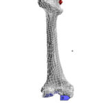 |
Figure 5: Loading of the Cracked Bone Click here to view Figure |
 |
Figure 6: Fatigue Analysis of Cracked Bone Click here to view Figure |
 |
Figure 7: Fatigue Analysis in Different parts of the Femur BoneClick here to view Figure |
Fatigue Analysis of Cracked Bone
The contour plot illustrates the distribution of fatigue life cycles within the bone and implant. The analysis indicates that the bone material can sustain up to 1×10⁶ ( 1 Mega)load cycles under the applied 600 N load. The contour plot highlights the regions of the bone and implant that are most susceptible to fatigue failure. Areas with lower life cycle counts indicate potential failure points.
Based on the contour plot and fatigue properties from literature, the bone-implant assembly is predicted to withstand up to 1e6 load cycles without failure. This demonstrates the durability of the implant under typical loading conditions experienced by elderly patients.
Discussion
The fatigue analysis, incorporating bonded contact between the bone and screw surfaces, reveals that the bone material can sustain up to 1×10⁶ (1 Mega)load cycles for a 60 kg load(Figure 8). The contour plot of life cycles (Figure 9) provides a detailed visualization of the fatigue life distribution, confirming the long-term performance and reliability of the bone-implant assembly. Table 2 represents life cycle parameters of the bone.. This analysis is critical for ensuring the safety and effectiveness of the implant in elderly patients with proximal femur fractures.
Factor of Safety for Bone in different region. Minimum factor of safety is 5 which is observed in middle portion of the bone.
For example: If a femur’s maximum allowable stress (failure strain level) is 180 N/mm² and the peak functional strain is 30 N/mm², the safety factor would be 180/30 = 6
Minimum factor of safety is 5 which is observed in middle portion of the bone(Figure 10). Lower safety factors and an increased risk of fracture can result from osteoporosis’s substantial reduction in bone density and strength, but osteoporosis parameter were not considered for our work.
The factor of Safety of different parts of Implant and regions of Femur Bone are shown in Figure in 11 and Figure 12.
 |
Figure 8 : Life Cycles of the Bone with Scale Click here to view Figure |
Table 2: Life Cycle Parameters of Bone
| Sr No | Parameters | Values/Ranges |
| 1 | Load Cycle | Up to 1M cycles |
| 2 | Allowable Range of Fatigue | 0 to 1M Cycles |
| 3 | Extreme values of fatigue | ≥ 1M Cycles |
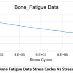 |
Figure 9: Bone Fatigue Data Stress Cycles Vs Stress(S-N Curve).Click here to view Figure |
 |
Figure 10: Factor of Safety in Cracked BoneClick here to view Figure |
 |
Figure 11: Factor of Safety in Different parts of the ImplantClick here to view Figure |
Factor of safety in different bone region
 |
Figure 12: Factor of safety in Proximal, Shaft and Knee RegionsClick here to view Figure |
Cracked Bone vs. Operated Bone
 |
Figure 13: Comparision of Operated Bone and Cracked BoneClick here to view Figure |
 |
Figure 14: Comparision of Factor of Safety pre and Post operationClick here to view Figure |
Factor of safety is increased after implant operation. Lifer cycles of operated (1.06*106) > cracked bone (8.8*105) graphically represented by Figure 13. It indicates that use of implant in virtual operation helps to increase fatigue life by distributing load more evenly and reducing local stress which may leads to premature failure. This indicates effectiveness implant in absorbing the load leveraging time for recovery of the fracture. This helps for Osseointegration and reducing stress concentration at bone –implant interface. Additionally, this study uses a thorough virtual simulation technique to show the effectiveness of Dynamic Hip Screw (DHS) stabilization in older patients with proximal femur fractures. To guarantee clinical relevance, the study involved clinical discussions with orthopedic surgeons. Finite Element Analysis (FEA) was utilized to investigate the mechanical behavior and patterns of stress distribution of the DHS implant under different loading scenarios. According to the Factor of Safety (FoS) calculations, there was a notable improvement in femur stability and structural integrity after surgery
Conclusion
In addition, this study demonstrates the efficacy of DHS( Dynamic Hip Screw) stabilization in elderly patients with proximal femur fractures using a comprehensive virtual simulation technique. Clinical consultations with orthopedic surgeons were included in the study to ensure clinical relevance. Under static loading conditions, since immediately post operatively patients only allowed to move or bend not walking or climbing stairs which is not a part of research. Finite Element Analysis (FEA) was used to examine stress distribution patterns and mechanical behavior of the DHS implant. A significant improvement in femur stability and structural integrity was observed following surgery, as revealed by the FoS computations (Figure 14). DHS stabilization improves load distribution and lowers complications, as demonstrated by the significant increase in overall FoS following DHS stabilization. Consequently, DHS stabilization emerged as a reliable and optimal management method. The operational structure is most stable when the factor of safety is larger than 5, and it is deemed unstable below that threshold, according to a comparison of the factor of safety and ultimate strength. The orthopedic surgeon may decide to allow the patient to experience increased loading situations. Both before and after the surgery, the simulation showed a highly good impact on the safety factor. It was found that the patient sample’s safety factor had greatly improved following the procedure, indicating the effectiveness of the suggested strategy. If this safety factor is less than 5, surgery with a different implant is permitted; nevertheless, this type of procedure requires clinical confirmation for improved efficacy. As a researcher, the study’s primary focus is on simulation rather than real-world implementation. The limitations of the virtual operation may include inability to replicate complex Vivo- loading conditions, regeneration process, need for careful consideration of individual specific factors. And possibility of implant failures. Margin of factor of safety needs to be carefully considered and balanced with complexity of factors.
Acknowledgement
The authors would like to thank our research Centre, S.K.N Sinhgad College of Engineering Korti, Pandharpur, India, for their assistance whenever possible, as well as Mr Shriram Kakade, a recognized expert, for validating the work.
Funding Source
The author(s) received no financial support for the research, authorship, and/or publication of this article.
Conflict of Interest
The author(s) do not have any conflict of interest.
Data Availability Statement
This statement does not apply to this article.
Ethics Statement-
This research did not involve human participants, animal subjects, or any material that requires ethical approval.
Informed Consent Statement
This study did not involve human participants, and therefore, informed consent was not required.
Clinical Trial Registration
This research does not involve any clinical trials
Permission to reproduce material from other sources
Not Applicable
Authors’ Contributions
- Aashish Joshi: Investigation, writing—original draft, writing—review and editing, formal analysis.
- Kailash Karande: Conceptualization, methodology, investigation, supervision, writing—review and editing,
- Ravindra Gunaki: Project administration, resources, supervision, writing—review and editing, and validation
References
- Balasubramani V., Gokul D. and Gokul R. K Modelling and finite element analysis of fractured femur bone with locking compression plate under fatigue load condition, Materials Today: Proceedings, 2023
CrossRef - Mathukumar S., Nagarajan V., and Radhakrishnan A Analysis and validation of femur bone data using finite element method under static load condition, Proceedings of the Institution of Mechanical Engineers, Part C: Journal of Mechanical Engineering Science. 2019 ;233(16):5547-5555.
CrossRef - Joshi A. and Karande K., Comprehensive survey on analysis and modelling of femur bone fracture for an operative planning, Computer Methods in Biomechanics and Biomedical Engineering: Imaging & Visualization, 2022 ; 11(4):1408–1417.
CrossRef - Biewener, A,Safety factors in bone strength,Calcified Tissue International, 1993;53(S1):S68–S74.
CrossRef - Taddei F., Palmadori I., Taylor W., Heller M., Bordini B., Toni A., and Schileo E. European Society of Biomechanics S.M. Perren Award 2014: Safety factor of the proximal femur during gait: a population-based finite element study, Journal of Biomechanics, 2014; 47(14): 3433–3440.
CrossRef - Barros M. A. M. de, Manzoli, O. L, and Bitencourt, L. A. G., Jr. Computational modeling of cracking in cortical bone microstructure using the mesh fragmentation technique, Archive of Applied Mechanics, 2024; 94(9): 2583–2601.
CrossRef - Jepsen and Davy D. T. Comparison of damage accumulation measures in human cortical bone, Journal of Biomechanics, 1997;30(9): 891–894.
CrossRef - Ramanath S. K., Shah R. H. and Kaushik, K. Conjoint removal of hip screw-femur head during hip replacement after previous dynamic hip screw fixation, Orthopaedic Surgery,2018; 10(4): 337–342.
CrossRef - Schwartsmann, C. R., Jacobus, L. S., Spinelli de F., Boschin, L. C., Gonçalves R, Z,, Yépez, A, and Silva M. F. Dynamic hip screw for the treatment of femoral neck fractures: a prospective study with 96 patients, ISRN Orthopedics, 2014; 257871.
CrossRef - Amalraju D. and Dawood A. S., Mechanical strength evaluation analysis of stainless steel and titanium locking plate for femur bone fracture. Eng Sci Technol Int J2012; 2(3): 381–388
- Godbole N., Yadav S., Ramachandran and Belemkar S. A., review on surface treatment of stainless steel orthopedic implants. Int. J. Pharm. Sci. Rev. Res. 2016; 36: 190–194.
- Buttaro, M. A., Comba F. and Piccaluga Proximal femoral reconstructions with bone impaction grafting and metal mesh. Clinical Orthopaedics and Related Research, 2009;467 (9):2325–2334.
CrossRef - Takigami I., Otsuka H., Yamamoto K., Iwase T., Fujita H., Matsuda S.and Akiyama H., Proximal femoral reconstruction with impaction bone grafting and circumferential metal mesh. J Orthop Sci. 2015 ;20(2):331-9.
CrossRef - Gracia L., Ibarz , Cegoino J.., Lobo-Escolar A, Gabarre S., Purtolas S., and Herrer, A Simulation by finite elements of bone remodeling after implantation of femoral stems, In Finite Element Analysis – From Biomedical Applications to Industrial Developments. 2012; 217-250.
CrossRef - Lee Y. S., Huang H. L., Lo T. Y. and Huang C.R.., Dynamic hip screw in the treatment of intertrochanteric fractures: a comparison of two fixation methods, Int Orthop. 2007 ;31(5):683-8
CrossRef - Wu H-F, Chang C-H, Wang G-J, Lai K.-A and Chen C-H, Biomechanical investigation of dynamic hip screw and wire fixation on an unstable intertrochanteric fracture, Biomedical Engineering Online, 2019; 18(1).
CrossRef - Cegoñino J., García Aznar J. M., Doblaré M., Palanca D., Seral B. and Seral F. A. comparative analysis of different treatments for distal femur fractures using the finite element method, Computer Methods in Biomechanics and Biomedical Engineering, 2004;7(5): 245–256.
CrossRef - Ahirwar H., Gupta V. K., and Nanda H. Finite element analysis of fixed bone plates over fractured femur model.Computer Methods in Biomechanics and Biomedical Engineering ; 2021; 24(15):1742–1751.
CrossRef - Patil J. S., Jadhav S. D. , Teli S. N., Kanse S. S., Surwade M. , Mhatre , Shinde A. and Tambe S FEA Analysis for Femur Bone Implant ,International Journal of All Research Education and Scientific Methods(IJARESM),2023;11(5):2455-6211.
- Nareliya R.and Kumar V., Biomechanical Analysis Of Human Femur Bone ,.International Journal of Engineering Science and Technology (IJEST),2011;3( 4) :3090-3094.
- Joshi A., Karande K., and Gunaki R. FEA-based virtual operation and stress distribution analysis of DHS screws in proximal femoral bone fractures: A strategic guide for orthopedic surgeons in operational planning. Journal of Pharmacology & Pharmacotherapeutics. 2024;0(0).
CrossRef - Jung C.H., Cha Y., Yoon H.S., Park C.H., Yoo J.I., Kim J.T., Jeon Y. Mechanical effects of surgical variations in the femoral neck system on Pauwels type III femoral neck fracture: a finite element analysis. Bone Joint Res., 2022;11(2):102-111. doi: 10.1302/2046-3758.112
CrossRef

