Manuscript accepted on :26-10-2023
Published online on: 01-10-2024
Plagiarism Check: Yes
Reviewed by: Dr. Bhavana Gundavarapu
Second Review by: Dr. Niharika Kondepudi
Final Approval by: Dr. Ian James Martin
Radhika Chellasamy1, Sathish Thanikodi2 , Kamesh Krishnamoorthy3, Gnanavel Balakrishnan Kannaiyan4 , Ragavanantham Shanmugam5
  and Monsuru Ramoni6
1Department of Mechanical Engineering, Saveetha Engineering College, Thandalam, Chennai, Tamil Nadu, India.
2Department of Thermal Engineering, Saveetha School of Engineering, Chennai, Tamil Nadu, India.
3Tool and Die Making, Murugappa Polytechnic College, Chennai, Tamil Nadu, India.
4Department of Mechanical Engineering, Faculty of Engineering and Technology, SRM Institute of Science and Technology, Kattankulathur.Tamil Nadu, India.
5Department of Engineering and Technology, Fairmont State University, West Virginia, United States of America.
6Industrial Engineering, Navajo Technical University, NM, United States of America.
Corresponding Author E-mail: radhikasky35@gmail.com
DOI : https://dx.doi.org/10.13005/bpj/2987
Abstract
To facilitate the delivery of drugs into the skin structure, microneedles play a pivotal role. Unlike conventional hypodermic syringes, microneedles penetrate only the dermis layer, avoiding nerve receptors and resulting in a painless injection. However, when a drug is administered into the skin, microneedles may undergo bending and buckling, leading to structural failure. Such failure can cause the drug to remain beneath the skin, potentially creating complications. Preventing the catastrophe of microneedle failure necessitates a close examination of parameters involved in the bending and buckling process. In this paper, we focus on buckling analysis, as the majority of microneedle failures are attributed to the buckling effect. We perform buckling analysis through finite element analysis to predict the critical buckling load (Pcr). This analysis helps determine the maximum load that a microneedle can withstand. We conduct this analysis using two modes: linear and non-linear (post-buckling analysis). By varying the tip diameter of the microneedle (20µm, 40µm, 60µm, 80µm, 100µm), we can identify the safe insertion load.
Keywords
Buckling analysis; Critical buckling load; Finite element analysis; Polycarbonate microneedle; post-buckling behavior
Download this article as:| Copy the following to cite this article: Chellasamy R, Thanikodi S, Krishnamoorthy K, Kannaiyan G. B, Shanmugam R, Ramoni M. Linear and Post-Buckling Analysis of Biocompatible Polymer Microneedle for Transdermal Drug Delivery. Biomed Pharmacol J 2024;17(3). |
| Copy the following to cite this URL: Chellasamy R, Thanikodi S, Krishnamoorthy K, Kannaiyan G. B, Shanmugam R, Ramoni M. Linear and Post-Buckling Analysis of Biocompatible Polymer Microneedle for Transdermal Drug Delivery. Biomed Pharmacol J 2024;17(3). Available from: https://bit.ly/3Y8U1xm |
Introduction
Microneedles are utilized to deliver drugs through micron-sized patches. These patches are meticulously designed so that when applied to the skin, the micron-sized needles penetrate the skin to deliver the drug. The microneedles only reach up to the dermis layer, ensuring a painless dose. While a variety of microneedles are available today, the development of a painless and safe needle remains a challenging process. Microneedles are classified based on the fabrication process, shapes, types, drug delivery approaches, and materials. Regarding the fabrication process, microneedles can be categorized as in-plane and out-of-plane microneedles1, 2, 3, 4. The variation depends on the needles which protrude in and out of the base surface. A variety of microneedle shapes is reported in the literature such as cylinder, cone, pyramid, tapered, and several shapes as mentioned in Table I5. Based on the types and drug delivery approach, the microneedles consist of solid, coated, hollow, and dissolving microneedles. The solid microneedles work by generating pores on the skin by insertion thereby applying the drug to the skin 6,7. The coated microneedles encompass solid microneedle coated with the drug. The coating of drugs is demonstrated by a predictable film coating process 8. The hollow microneedles are intended to generate a hollow path for carrying and delivering the drug 8,9,10. The dissolving microneedles are designed in such a way the needles gets dissolved once it is injected into the skin 11, 12.
Table 1: Classification of microneedles based on the shapes.
|
Geometrical shape |
References |
|
Cylinder |
13, 14, 15 |
|
Cone |
16, 17, 14, 18, 19, 20, 21 |
|
Pyramid |
Square – 22, 20, 23, 24, 25 |
|
Triangular – 26, 27 |
|
|
Octahedral- 28 |
|
|
Tapered |
29, 30, 31,32, 13 |
|
Spear |
24, 7 |
|
Spherical pedestal |
33 |
|
Candle-like |
7, 34 |
|
Bullet-shaped |
35, 36, 37 |
|
Spike |
4, 38, 7 |
|
Lancet |
14 |
Table 2: Material properties
|
Structure |
Material |
Young’s modulus, E |
Density, ρ |
Poisson ratio, ν |
Ultimate stress, σut |
References |
|
Unit |
– |
GPa |
kg/m3 |
– |
MPa |
– |
|
Microneedle |
Polycarbonate |
2.4 |
1200 |
0.37 |
55 |
39 |
|
Silicon |
162 |
2330 |
0.22 |
700 |
40 |
|
|
168.9 |
2329 |
0.3 |
– |
41 |
||
|
Skin |
Aluminium |
70 |
2660 |
0.3 |
275 |
42 |
|
Porcine skin |
0.00435 |
– |
– |
– |
43 |
Materials and Methods
Microneedles are made from a variety of materials, including silicon, glass, metal, composites, and polymers. The current trend in microneedle development places a strong emphasis on polymer materials to create biocompatible microneedles for safe insertion. The selection of the polymer material for microneedles is contingent upon the specific drug, the type of disease being treated, and the desired immune response. 44, 45. The polymer material selection and the guidelines for the appropriate fabrication process is discussed 46. The polycarbonate a biocompatible polymer microneedle is selected for predicting the structural behavior using the numerical technique. The geometrical dimensions of the cone-shaped microneedle is considered as a reference from the literature 47. The properties applied to the microneedle are listed in Table II.
Theoretical study: Microneedle Buckling Effect
The buckling behavior of a microneedle is primarily determined by its length, yield strength, and tip diameter. Longer microneedles with lower yield strength are more likely to experience buckling 48. Once the needle starts to buckle, further increasing the applied load will make the microneedle critically buckle leading to fracture 48. The tip diameter as well depends on the buckling effect. Having a sharp tip, the microneedle effortlessly gets inserted into the skin thereby preventing the buckling effect 49. As the majority of the microneedle failure is caused by buckling, identifying the buckling causing parameters and controlling the effects will lead to a safe insertion. The theoretical study in predicting the critical buckling actions is deliberated 50.
The bending moment equation in predicting the critical load is given as (1).

The critical buckling load (Pcr)considered for the tapered structure is given as 51 in equation (2)

The critical buckling load derived for the hollow conical structure is specified from equation (1) as 32.

Numerical Analysis
Linear Buckling Analysis
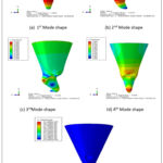
Buckling analysis of the microneedle is conducted using two methods: linear buckling mode with a linear perturbation procedure in the Abaqus module and non-linear buckling using the Static Riks algorithm. In the linear buckling analysis, the microneedle is meshed using the C3D10 – 10-node quadratic tetrahedron element, effectively discretizing the model. To apply loads consistently on the microneedle structure, a reference point is created on the top surface of the microneedle. Initially, a 1N load is applied to the top reference point, and the bottom surface is constrained to arrest all degrees of freedom. This analysis is carried out for microneedle tip diameters of 20µm, 40µm, 60µm, 80µm, and 100µm. The results obtained from the linear buckling analysis for various tip diameters are presented in Table III, which includes eigenvalues, reaction forces, displacements, and displacement rotations. As the tip diameter increases, the eigenvalue also increases, while the reaction force, displacement, and displacement rotation vary. Critical buckling loads are determined for each diameter using the linear technique: Pcr (20 µm) = 0.50183, Pcr (40 µm) = 1.7563, Pcr (60 µm) = 3.5228, Pcr (80 µm) = 5.4135, and Pcr (100 µm) = 7.2427. The findings indicate that for a 60 µm tip diameter, the reaction force is minimized, and displacement is maximized compared to other tip diameters. Mode shapes for the 60 µm tip diameter are illustrated in Figure 1. This analysis highlights the importance of ensuring that the applied load for each diameter remains below the critical load to guarantee a safe insertion.
Table 3: Linear buckling results exerted for various tip diameter
|
Tip Diameter (Td), µm |
Eigen value |
Reaction Force (RF), N |
Displacement (U), µm |
Displacement Rotation (UR), N |
|
20 |
0.50183 |
2.648 |
501.83 |
2.020 |
|
40 |
1.7563 |
3.455 |
1067 |
1.442 |
|
60 |
3.5228 |
1.169 |
1183 |
2.02 |
|
80 |
5.4135 |
4.105 |
1040 |
2.199 |
|
100 |
7.2427 |
6.401 |
1029 |
1.881 |
 |
Figure 1: Various mode shapes obtained during the linear buckling analysis for microneedle tip diameter, Td=60 µm. |
Post-buckling Analysis
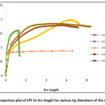
The non-linear buckling analysis, also known as post-buckling analysis, is conducted using the Static-Riks algorithm. The critical buckling load obtained from the linear analysis serves as the input load for the post-buckling analysis, with 1000 iterations specified. For each diameter, an individual Load Proportionality Factor (LPF) graph is generated and compared, as depicted in Figure 2. Notably, the 60 µm diameter exhibits faster convergence within minimal arc length increments compared to other diameters. The initial buckling of the 60 µm diameter microneedle occurs at the 5th iteration, with the corresponding Critical Force (CF), Reaction Force (RF), Displacement (U), and Displacement Rotation (UR) values of 0.289115, 8.20E-05, 0.007601 mm, and 0.001714 radians, respectively. At the 712th iteration, the microneedle enters a critical buckling state, with CF, RF, U, and UR values of 0.558693, 0.017281, 0.087769 mm, and 0.096524 radians. During this critical buckling stage, the specified Load Proportionality Factor (LPF) is 0.159626, representing 15.96% of the applied load. Hence, the critical buckling load is calculated as the product of the LPF and the applied load. This approach is applied consistently across all tip diameters to determine the critical load
Pcr (20ɸ) = 0.0908014x 0.50183 N = 0.0455N
Critical buckling load, Pcr(20ɸ) = 0.05 N
Pcr (40ɸ) = 0.19699x 1.7563 N = 0.3459N
Critical buckling load, Pcr (40ɸ) = 0.3 N
Pcr (60ɸ) = 0.159626x 3.5228 N = 0.558691N
Critical buckling load, Pcr (60ɸ) = 0.6 N
Pcr (80ɸ) = 0.17829x 5.4135 N = 0.965N
Critical buckling load, Pcr (80ɸ) = 1 N
Pcr (100ɸ) = 0.184288x 7.2427 N = 1.334N
Critical buckling load, Pcr (100ɸ) = 1.3 N
Exceeding the critical buckling load leads to structural failure in the microneedle, resulting in a severe buckling effect. Therefore, it is essential to ensure that the applied load for insertion remains below the corresponding critical buckling load obtained for each diameter.
 |
Figure 2: Comparison plot of LPF Vs Arc length for various tip diameters of the microneedle. |
Result and Discussion
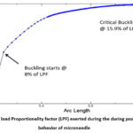
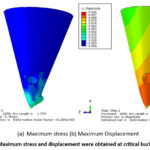
Non-linear buckling analysis is performed to anticipate the post-buckling response of the microneedle under various loading conditions. Among the different tip diameters examined, only the 60 µm tip microneedle displayed superior convergence. The Load Proportionality Factor (LPF) graph for the 60 µm tip diameter microneedle is depicted in Figure 3. Initial buckling initiates at 8% of the applied load, reaching a critical buckling point at 15.9% of the applied load. The corresponding critical buckling load is calculated as 0.6N. Therefore, for safe insertion, the microneedle should not be subjected to loads exceeding 0.6N. To gain further insight, the microneedle’s behavior is scrutinized to identify the maximum failure points at the critical stage. The maximum stress and displacement, recorded at the 712th iteration, are found to be 176.483N/mm² and 0.106mm, as illustrated in Figure 4. Importantly, even at critical points, it is observed that the microneedle’s tip does not fracture but instead undergoes crushing, ultimately leading to failure.
 |
Figure 3: The load Proportionality factor (LPF) exerted during the during post buckling behavior of microneedle |
 |
Figure 4: Maximum stress and displacement were obtained at critical buckling points. |
Conclusion
The stability of microneedles is at risk when the insertion force surpasses a certain threshold, known as the critical load. To ensure their safe application, it is imperative to identify this critical load for structures that are vulnerable to buckling. This is achieved through both linear and non-linear (post-buckling) analyses using numerical Finite Element Analysis (FEA) software. These analyses reveal that the critical buckling loads for microneedles are 3.5228N for linear analysis and 0.6N for post-buckling analysis. These values are evaluated across different tip diameters, providing a comprehensive understanding of the safe insertion loads. This methodology can be extended to various structures at risk of buckling, enhancing their safety under applied loads. Additionally, these findings are pertinent to the insertion of microneedles into human skin, ensuring their effective and safe use in medical applications.
Acknowledgment
The author would like to thank, (Insert university name and Dept. name) for their guidance and support to complete this article.
Conflict of Interest
The authors do not have any conflict of interest.
Funding Sources
The author(s) received no financial support for the research, authorship, and/or publication of this article.
Data Availability Statement
This statement does not apply to this article.
Ethics Statement
This research did not involve human participants, animal subjects, or any material that requires ethical approval.
References
- Chen J, Wise KD, Hetke JF, Bledsoe SC. A multichannel neural probe for selective chemical delivery at the cellular level. IEEE Trans Biomed Eng. 1997;44(8):760-769. doi:10.1109/10.605435
CrossRef - BeMent SL, Wise KD, Anderson DJ, Najafi K, Drake KL. Solid-State Electrodes for Multichannel Multiplexed Intracortical Neuronal Recording. IEEE Trans Biomed Eng. 1986;BME-33(2):230-241. doi:10.1109/TBME.1986.325895
CrossRef - Brazzle J, Bartholomeusz D, Davies R, Andrade J, Frazier a B, Wagenen R a Van. Active Microneedles with Integrated Functionality. Hilt Head. 2000;(February 2014):4-7.
CrossRef - Griss P, Stemme G. Novel, side opened out-of-plane microneedles for microfluidic transdermal interfacing. Tech Dig MEMS 2002 IEEE Int Conf Fifteenth IEEE Int Conf Micro Electro Mech Syst (Cat No02CH37266). 2002:467-470. doi:10.1109/MEMSYS.2002.984303
CrossRef - Ashraf MW, Tayyaba S, Afzulpurkar N. Micro Electromechanical Systems (MEMS) based microfluidic devices for biomedical applications. Int J Mol Sci. 2011;12(6):3648-3704. doi:10.3390/ijms12063648
CrossRef - Kaushik S, Hord a H, Denson DD, et al. Lack of pain associated with microfabricated microneedles. Anesth Analg. 2001;92:502-504. doi:10.1213/00000539-200102000-00041
- Shikida M, Odagaki M, Todoroki N, et al. Non-photolithographic pattern transfer for fabricating arrayed three-dimensional microstructures by chemical anisotropic etching. Sensors Actuators, A Phys. 2004;116(2):264-271. doi:10.1016/j.sna.2004.04.031
CrossRef - McGrath MG, Vrdoljak A, O’Mahony C, Oliveira JC, Moore AC, Crean AM. Determination of parameters for successful spray coating of silicon microneedle arrays. Int J Pharm. 2011;415(1-2):140-149. doi:10.1016/j.ijpharm.2011.05.064
CrossRef - Rodríguez A, Molinero D, Valera E, et al. Fabrication of silicon oxide microneedles from macroporous silicon. Sensors Actuators, B Chem. 2005. doi:10.1016/j.snb.2005.03.015
CrossRef - Ovsianikov A, Chichkov B, Mente P, Monteiro-Riviere NA, Doraiswamy A, Narayan RJ. Two photon polymerization of polymer-ceramic hybrid materials for transdermal drug delivery. Int J Appl Ceram Technol. 2007;4(1):22-29. doi:10.1111/j.1744-7402.2007.02115.x
CrossRef - Liu S, Jin MN, Quan YS, et al. Transdermal delivery of relatively high molecular weight drugs using novel self-dissolving microneedle arrays fabricated from hyaluronic acid and their characteristics and safety after application to the skin. Eur J Pharm Biopharm. 2014. doi:10.1016/j.ejpb.2013.10.001
CrossRef - Yang H, Wu X, Zhou Z, Chen X, Kong M. Enhanced transdermal lymphatic delivery of doxorubicin via hyaluronic acid based transfersomes/microneedle complex for tumor metastasis therapy. Int J Biol Macromol. 2018:#pagerange#. doi:10.1016/j.ijbiomac.2018.11.230
CrossRef - Chua B, Desai SP, Tierney MJ, Tamada JA, Jina AN. Effect of microneedles shape on skin penetration and minimally invasive continuous glucose monitoring in vivo. Sensors Actuators, A Phys. 2013;203:373-381. doi:10.1016/j.sna.2013.09.026
CrossRef - Dardano P, Caliò A, Di Palma V, Bevilacqua MF, Di Matteo AD, Stefano L. A photolithographic approach to polymeric microneedles array fabrication. Materials (Basel). 2015;8(12):8661-8673. doi:10.3390/ma8125484
CrossRef - Mishra R, Maiti TK, Bhattacharyya TK. Design and scalable fabrication of hollow SU-8 microneedles for transdermal drug delivery. IEEE Sens J. 2018;18(14):5635-5644. doi:10.1109/JSEN.2018.2840335
CrossRef - Lee K, Lee CY, Jung H. Dissolving microneedles for transdermal drug administration prepared by stepwise controlled drawing of maltose. Biomaterials. 2011. doi:10.1016/j.biomaterials.2011.01.014
CrossRef - Yang SY, O’Cearbhaill ED, Sisk GC, et al. A bio-inspired swellable microneedle adhesive for mechanical interlocking with tissue. Nat Commun. 2013;4:2-11. doi:10.1038/ncomms2715
CrossRef - Reddy Mogusala N, Ratnam Devadasu V, Kumar Venisetty R. American Journal of Drug Delivery and Therapeutics Fabrication of Microneedle Molds and Polymer Based Biodegradable Microneedle Patches: A Novel Method. Am J Drug Deliv Ther. 2015. http://www.imedpub.com/ articles/ fabrication-of-microneedle-molds-andpolymer-based-biodegradable-microneedlepatches-a-novel-method.pdf.
CrossRef - Machekposhti SA, Soltani M, Najafizadeh P, Ebrahimi SA, Chen P. Biocompatible polymer microneedle for transdermal delivery of tranexamic acid. J Control Release. 2017. doi:10.1016/j.jconrel.2017.06.016
- Pere CPP, Economidou SN, Lall G, et al. 3D printed microneedles for insulin skin delivery. Int J Pharm. 2018. doi:10.1016/j.ijpharm.2018.03.031
CrossRef - García-López E, Siller HR, Rodríguez CA. Study of the fabrication of AISI 316L microneedle arrays. Procedia Manuf. 2018;26:117-124. doi:10.1016/j.promfg.2018.07.014
CrossRef - Ji J, Tay FEH, Miao J, Iliescu C. Microfabricated microneedle with porous tip for drug delivery. J Micromechanics Microengineering. 2006;16(5):958-964. doi:10.1088/0960-1317/16/5/012
CrossRef - McConville A, Davis J. Transdermal microneedle sensor arrays based on palladium: Polymer composites. Electrochem commun. 2016;72:162-165. doi:10.1016/j.elecom.2016.09.024
CrossRef - Economidou SN, Patricia C, Pere P, et al. 3D printed microneedle patches using stereolithography (SLA) for intradermal insulin delivery. Mater Sci Eng C. 2019. doi:10.1016/j.msec.2019.04.063
CrossRef - Senel M, Dervisevic M, Voelcker NH. Gold microneedles fabricated by casting of gold ink used for urea sensing. Mater Lett. 2019;243(February):50-53. doi:10.1016/j.matlet.2019.02.014
CrossRef - Valdés-Ramírez G, Windmiller JR, Claussen JC, et al. Multiplexed and switchable release of distinct fluids from microneedle platforms via conducting polymer nanoactuators for potential drug delivery. Sensors Actuators, B Chem. 2012;161(1):1018-1024. doi:10.1016/j.snb.2011.11.085
CrossRef - Mohan AMV, Windmiller JR, Mishra RK, Wang J. Continuous minimally-invasive alcohol monitoring using microneedle sensor arrays. Biosens Bioelectron. 2017;91:574-579. doi:10.1016/j.bios.2017.01.016
CrossRef - Das A, Singha C, Bhattacharyya A. Microelectronic Engineering Development of silicon microneedle arrays with spontaneously generated micro-cavity ring for transdermal drug delivery. Microelectron Eng. 2019;210(March):14-18. doi:10.1016/j.mee.2019.03.019
CrossRef - Jung-Hwan Park, Yong-Kyu Yoon, Prausnitz MR, Allen MG. High-aspect-ratio tapered structures using an integrated lens technique. IEEE. 2004:383-386. doi:10.1109/mems.2004.1290602
CrossRef - Yu H, Du R, Guo Y, Wang Y, Di S. Fabrication of taper hollow metallic microneedle array for portable drug delivery system. 2010 IEEE 5th Int Conf Nano/Micro Eng Mol Syst NEMS 2010. 2010:676-679. doi:10.1109/NEMS.2010.5592495
CrossRef - Yan XX, Liu JQ, Jiang SD, Yang B, Yang CS. Fabrication and testing analysis of tapered silicon microneedles for drug delivery applications. Microelectron Eng. 2013;111:33-38. doi:10.1016/j.mee.2013.04.039
CrossRef - Kim K, Park DS, Lu HM, et al. A tapered hollow metallic microneedle array using backside exposure of SU-8. J Micromechanics Microengineering. 2004:597-603. doi:10.1088/0960-1317/14/4/021
CrossRef - Ruggiero F, Vecchione R, Bhowmick S, et al. Electro-drawn polymer microneedle arrays with controlled shape and dimension. Sensors Actuators B Chem. 2017. doi:10.1016/j.snb.2017.08.165
CrossRef - Arai M, Kudo Y, Miki N. Polymer-based candle-shaped microneedle electrodes for electroencephalography on hairy skin. Jpn J Appl Phys. 2016;55(6). doi:10.7567/JJAP.55.06GP16
CrossRef - Seong KY, Seo MS, Hwang DY, et al. A self-adherent, bullet-shaped microneedle patch for controlled transdermal delivery of insulin. J Control Release. 2017;265(October 2016):48-56. doi:10.1016/j.jconrel.2017.03.041
CrossRef - Lee K, Park SH, Lee J, Ryu S, Joo C, Ryu W. Three-step thermal drawing for rapid prototyping of highly customizable microneedles for vascular tissue insertion. Pharmaceutics. 2019;11(3). doi:10.3390/pharmaceutics11030100
CrossRef - Chandrasekharan, Hwang, Seong, Park, Kim, Yang. Acid-Treated Water-Soluble Chitosan Suitable for Microneedle-Assisted Intracutaneous Drug Delivery. Pharmaceutics. 2019;11(5):209. doi:10.3390/pharmaceutics11050209
CrossRef - Griss P, Enoksson P, Stemme G. Barbed spike arrays for mechanical chip attachment. 2002:46-49. doi:10.1109/memsys.2001.906475
CrossRef - Sausse Lhernould M, Delchambre A. Innovative design of hollow polymeric microneedles for transdermal drug delivery. Microsyst Technol. 2011;17(10-11):1675-1682. doi:10.1007/s00542-011-1355-2
CrossRef - Cui Q, Liu ÆC, Zha ÆXF. Study on a piezoelectric micropump for the controlled drug delivery system. 2007:377-390. doi:10.1007/s10404-006-0137-0
CrossRef - Ashraf MW, Tayyaba S, Nisar A, et al. Design, fabrication and analysis of silicon hollow microneedles for transdermal drug delivery system for treatment of hemodynamic dysfunctions. Cardiovasc Eng. 2010;10(3):91-108. doi:10.1007/s10558-010-9100-5
CrossRef - Koulocheris D V, Vossou CG. Alternative Design for a Semi Trailer Tank Vehicle. Mobil Veh Mech. 2018;44(December):51-69. doi:10.24874/mvm.2018.44.02.05
CrossRef - Kuropka P, Kobielarz M, Dudek A. Determination of the mechanical properties of the skin of pig foetuses with respect to its structure. Acta Bioeng Biomech. 2011;13(May 2014).
CrossRef - Nevagi RJ, Skwarczynski M, Toth I. Polymers for Subunit Vaccine Delivery. Eur Polym J. 2019;(March). doi:10.1016/j.eurpolymj. 2019.03.009
- Demir YK, Akan Z, Kerimoglu O. Characterization of Polymeric Microneedle Arrays for Transdermal Drug Delivery. PLoS One. 2013;8(10):1-9. doi:10.1371/journal.pone.0077289
CrossRef - Wang M, Hu L, Xu C. Recent advances in the design of polymeric microneedles for transdermal drug delivery and biosensing. Lab Chip. 2017;17(8):1373-1387. doi:10.1039/C7LC00016B
CrossRef - Lhernould MS ausse, Deleers M, Delchambre A. Hollow polymer microneedles array resistance and insertion tests. Int J Pharm. 2015;480(1-2):152-157. doi:10.1016/j.ijpharm.2015.01.019
CrossRef - Shetty S. Investigation of geometrical effects on microneedle reliability for transdermal applications. 2005.
- `Ashraf MW, Tayyaba S, Afzulpurkar N. MEMS based polymeric drug delivery system. 2010 IEEE Int Conf Autom Sci Eng CASE 2010. 2010:192-197. doi:10.1109/COASE.2010.5583941
CrossRef - Paik SJ, Byun S, Lim JM, et al. In-plane single-crystal-silicon microneedles for minimally invasive microfluid systems. Sensors Actuators, A Phys. 2004;114(2-3):276-284. doi:10.1016/j.sna.2003.12.029
CrossRef - Smith Garth W. Analytic solutions for tapered column buckling. Compufers It Slrucfures. 1988;28(5):677-681. doi:10.1016/b978-075067402
CrossRef
|
Nomenclature |
|
|
Mn |
Microneedle |
|
E |
Youngs Modulus |
|
σ |
Stress |
|
σut |
Ultimate stress |
|
ρ |
Density |
|
ν |
Poissons ratio |
|
Td |
Tip diameter |
|
Pcr |
Critical buckling load |
|
I(z) |
Moment of inertia about the centroid |
|
M(z) |
Bending moment distribution |
|
y(z) |
Deflected shape |
|
L |
Length of the column |
|
k |
Constant coefficient |
|
di |
Internal diameter |
|
do |
Outer diameter |
|
RF |
Reaction force |
|
U |
Displacement |
|
UR |
Displacement rotation |
|
LPF |
Load proportionality factor |


