
Shripad Bhatlawande , Swati Shilaskar* and Pranav Belgaonkar
Department of E and TC Engineering, Vishwakarma Institute of Technology, Pune, India
Corresponding Author E-mail: swati.shilaskar@vit.edu
DOI : https://dx.doi.org/10.13005/bpj/2950
Abstract
Prosthetic arms are worn by people whose arms have been amputated. Amputation involves surgical removal of the muscle, neurosensory system, and skeletal system. Myoelectric prosthetics make use of the signals generated by the intact muscles for the limb movement. Prosthetic limbs are designed using mechanical parts with suitable gear and motors. Users of prosthetic arms can carry out tasks associated with everyday living and their jobs almost exactly like they would with a natural arm. Prosthetic arms come in a variety of designs based on the needs of the user. The current research reviews the goals, plans, and trials conducted on prosthetic elbows, wrists, and hands between 2011 and 2022 from reputable conferences and journals. In this work, the design of two prosthetic hands with one degree of freedom and thirteen degrees of freedom, respectively, in the 3D simulation tool SolidWorks is described. Prosthetic elbow and a wrist with one degree of freedom were designed as well. The fine motor activities can be performed with the prosthetic fingers designed in this work.
Keywords
Prosthetic Arm; Prosthesis; Artificial hand; Myoelectric hand
Download this article as:| Copy the following to cite this article: Bhatlawande S, Shilaskar S, Belgaonkar P. A Review of Myoelectric Prosthetic Arm Designs from 2011 to 2022. Biomed Pharmacol J 2024;17(3). |
| Copy the following to cite this URL: Bhatlawande S, Shilaskar S, Belgaonkar P. A Review of Myoelectric Prosthetic Arm Designs from 2011 to 2022. Biomed Pharmacol J 2024;17(3). Available from: https://bit.ly/3yNu9Nv |
Introduction
The human hand is capable of incredibly delicate and accurate tasks like writing, painting, or threading a needle, as well as more strenuous tasks like lifting heavy weights or doing labour-intensive tasks. It has evolved such that it can grasp, feel, hold, manipulate, and so much more. As our hands allow us to communicate with the outside world, the brain devotes a great deal of energy to their operation 1. For this reason, recovery following an amputation may cause dissatisfaction and melancholy 2. Phantom pain, or pain seen as emanating from a missing bodily part, can be experienced by amputees 3. Amputations of the upper limb cause even more severe pain. Patients who had their limbs amputated because of an illness or accident may experience complications. Thus, it’s crucial to preserve physical fitness. Taking into account the patient’s mental health is as important since their commitment and motivation are vital to the rehabilitation process. It might happen that the amputee will not initially share his feelings, thus the therapist will need to ensure that the patient is expressing his feelings. Additionally, the doctor must make sure the patient is healing properly and assist the amputees with vocational training and placement if necessary4. After an amputation, the stump begins to shrink, and if the fitting is postponed for an extended period, the patient may choose not to wear a prosthesis at all. The early fitting is the best course of action for the patient’s recovery. In that instance, it is also important to inform the patient about the possibility of developing many sockets and the associated expenditures.
The phalanges or finger bones, the metacarpus and the carpus make up the three parts of the hand5. Three degrees of freedom (DOF) are available to the wrist: flexion/extension, pronation/supination, and radial/ulnar deviation. It consists of two interconnected joints. The hand’s midsection is called the metacarpus. Every finger is joined to a metacarpus bone. Except the thumb, which has two parts, all fingers have three parts: the DIP (distal interphalangeal joint), PIP (proximal interphalangeal joint), and MCP (metacarpal phalangeal joint). The thumb has two degrees of freedom because of its special joint with the metacarpus bone. There can be several reasons for performing an amputation. They may be brought on by illnesses like tetanus, which can be avoided by getting a booster shot every ten years6. Amputations due to infections have been observed to be extremely uncommon since the development of antibiotics. In low-income rural areas of India, amputations as a result of hazardous work equipment or conditions are commonplace7. The condition known as frostbite affects the extremities when they are exposed to extremely low temperatures. It can result in irreversible damage and cause the affected area to lose colour and feeling. Amputation may occur from frostbite in extreme circumstances8. Amputation of an arm or leg may be necessary in severe instances of primary bone cancer or soft tissue sarcoma. Compared to secondary bone cancer, which spreads to the bone from other parts of the body, primary bone cancer is a rarer form of cancer that begins in the bones9. Depending on the requirements of the user, a variety of prosthetics are offered in the market. Partial finger amputation is the term used when the amputation is restricted to the fingers or thumb. Any finger component, including the MCP, PIP, and DIP, can be replaced. The removal of the hand and wrist is known as disarticulation of the wrist. Elbow disarticulation is the removal at the elbow joint, trans-radial amputation is the amputation below the elbow, and transhumeral amputation is the amputation through the humerus, that is, above the elbow and below the shoulder 10. This paper focuses exclusively on shoulder-level amputation designs.
Passive prosthetics are those that have little to no mechanical components and can be attached for aesthetic reasons. They may have mechanisms that are operated with the other hand. Activities requiring two hands are made easier with the use of prosthetic tools like a hook. They can be customized to fit the amputee’s hands and made of PVC or various silicone qualities. Steel or plastic can be printed using 3D printing to create more recent models of prosthetic hands. Depending on the circumstance, amputees often use both passive and active hands. On social occasions, people use their passive hands to project confidence because they look more natural and are more comfortable than their active hands. They forget about the user’s handicap and provide psychological support.11.
Body-powered prosthetics are operated using harnesses and cables that are operated through the movement of the chest and shoulder. People who perform manual labour can use these prosthetics because they are sturdy and can support the other arm. Typically, the end effectors are hooks that can be either normally closed or normally open. These hooks can be lined with rubber for improved grip and are constructed from a variety of materials, including titanium and plastic. People with partial hand or finger loss use naked prosthetics, one type of body-powered prosthetic device. The end effectors are modular and can be changed easily for specific tasks. As body-powered hands are lighter than myoelectric hands, they can be used for much longer and are more comfortable. They can be used for travelling activities for extended durations as they are not dependent on batteries 12. Electronically operated prosthetics are the third category of prosthetic devices. They have sensors attached, such as an electromyography (EMG) or electroencephalogram (EEG) sensor, which picks up signals from the user’s body, interprets them as a desired action, and then sends commands to the end effectors, such as motors, in accordance with that interpretation. Depending on the needs of the user, there are several ways to design this kind of prosthetic. They can be fastened using a straightforward gripper that can open and close, or they can be fastened using a complex mechanism that can regulate each finger. Amputation of upper limbs is more frequent in developing countries and usually, people from those countries cannot afford expensive myoelectric arms so it is important for the research community to come up with solutions that can help the population of these countries during work and also be affordable 13 Three million people have had their arms amputated globally, with 2.4 million of those individuals residing in developing nations 14. A total of 0.11 million people in India were amputees in 2019 due to amputations below the elbow and an additional 16,500 are added annually6. A 1975 study found that 75% of amputees switch from labour-intensive jobs like processing and machining to sales or clerical work15. This demonstrates how an amputee’s lifestyle may change significantly after an amputation.
Literature Review
Galileo Hand16 was a 3D printed hand with a simple but effective design for trans radial amputation and a wide range of customization options based on the needs and financial constraints of the user. Its modular design allowed for easy modification to expand its target user base and its construction with materials readily available in developing nations made this possible. It weighed less than 350g and cost less than $350. Additionally, a micro-LCD screen was attached to the hand, displaying a variety of grip options for the user to choose from. For the benefit of amputees with stumps of any length, the entire mechanical assembly, a micro LCD screen and motors were affixed inside the hand itself. The actuators for the thumb, the motors for the fingers other than the thumb and the remaining parts, including the micro-LCD screen, were separated into three sections of the palm. It made use of an ARM Cortex-M4-based microcontroller with SIMD extensions to its instruction set for signal processing and stack pointers for RTOS (real-time operating system) applications implemented in real-time. Six degrees of freedom were present in the hand. The Thumb had two actuators, so it had two degrees of freedom. The thumb contained the actuator that controlled flexion and extension. The abduction-adduction mechanism was made up of a motor housed inside the palm and a bevel and helical gear system to alter the rotational axis. If the material is thermo-flexible, additional grip was provided by connecting the outer shell to the inner phalanx. Additionally, the finger’s length could be adjusted to the user’s preference. A tendon drive was used in the design of this finger actuation system. Elastic cords were utilized as passive tendons and waxed nylon cords as active tendons. The active tendons were inserted from the inner side and the passive tendons from the outer (dorsal) side; were joined at the fingertip. There were two ways to control the hand: one was with an EMG band and the other was with buttons and a Micro LED display. Tests were done to determine which interface would be easier for users to use and the EMG version performed marginally better because it required less work from the user. The authors chose to give the user access to both user interfaces after realizing that there were some drawbacks to this approach as well. As per17, the prosthetic design is based on the fact that the thumb is the most used finger in our daily lives and it is used 37.6% of the time followed by the middle finger at 21.2%, the index finger at 19.7% and ring and little finger at 5.6% and 2.4 % respectively18. So the design focused on attaining the maximum possible range of motion for the thumb, then the index and middle finger followed by the little and the ring finger. Attention was given to 2 types of grips namely power grip and precision grip as they are used a lot in daily life. The thumb was positioned in such a way that these grips were possible. A total of 2 motors are used, 1 for actuating the thumb to imitate the CM joint that moves the thumb towards the inside of the palm and the other is used for the rest of the fingers for flexion and extension. The fingertips were made of soft material to increase the contact area while picking up objects and grasping objects in a much more comfortable grip. The hand could also perform lateral grip. An added benefit was that it also allowed the user to pick up smaller objects as compared to what was possible before. The hand could provide 3 types of grips. The unique aspect of the design was its inclusion of a nail at the end of the finger presumably to make the prosthetic hand look more aesthetically similar to a human hand. Springs were added to the design in a newer version, to factor in any large impact to the hand that might damage the hand. The authors pointed out that if the impact was large enough, the deformation would be permanent without springs. These springs were put in at the MCP joint, where the finger was attached to the palm. The ‘Pick and Place’ experiment was conducted using objects used in daily life. They were to be lifted and placed at a target and back to the original point in 30 seconds. It was noted that the improved hand was able to pick up small objects better than the older version and the factors that contributed to this improvement was the shape of the nails and the spring.
Rehand 19 was a prosthetic hand that was 3D printed, had a single actuator and a basic mechanism that allowed it to grasp objects just like a real hand. The hand would be simple to construct and maintain because it was 3D printed. The SATO GIKEN corp. passive prosthetic hand served as the model for the hand. The next step involved developing the grasping mechanism using the CAD model as a basis. A linear actuator coupled to a number of shafts and links operated the mechanism. The control mechanism was unique compared to most prosthetic hands on the market. A distance sensor in the socket that is fixed to the stump measured the bulge of the muscles by calculating the separation between the sensor and the skin. A urethane spacer separated the distance sensor from the skin, preventing direct skin contact. The distance sensor computed the necessary amount of extension-flexion for the prosthetic arm by measuring the bulge of the muscles. Sweat could have an impact on EMG signals that were in contact with the skin, but Rehand fixed this drawback. Also, they are far less expensive than EMG sensors. To begin the hand calibration, press a button on the control box and hold it down for one second. The distance sensor would measure the arm’s resting distance over the course of the next one second and averaged it. The values were then averaged once more after the sensor recorded the data during contraction. A full calibration would take about five seconds. One could function passively with the wrist. With the assistance of an amputee skilled in using commercial prostheses, the Southampton Hand Assessment Procedure was carried out for this hand20, and the distance sensor was attached to his carpi ulnaris. Six abstract object tasks and eight simulated Activities in Daily Life (ADL) tasks made up the tasks, which had to be finished in 100 seconds. The individual succeeded in moving the three light objects, but was unable to use Rehand to finish the remaining abstract object task. He was also able to complete most of the ADL tasks except the ones that needed fine manipulation like picking up coins.
The design in21 was a 24 degree of freedom hand with hybrid actuation. The design was heavily inspired by the human hand by imitating the structure of a real hand, joints, muscles and tendons. Each part of the bone structure was studied carefully, recreated in CAD and scaled according to the requirements of the subject. Cylindrical joints were used for MCP, DIP, PIP of fingers and IP and CMC joint of the thumb, whereas spherical joint for MCP and CMC joint for the thumb. The design was influenced by constraints that the human hand provided. For instance, the design took into account the PIP joint’s limited extension-flexion range of 0 to 110 degrees in the human body. For finger abduction and adduction, shape memory alloy (SMA) actuators were positioned on the medial and lateral sides of the metacarpal. SMA was selected for this task because they could replicate the real muscles, which are lighter than motors and relatively weak. Brushless DC motors were used to flex and extend the prosthetic hand because their functionality was comparable to that of a real hand. Two additional motors were used for wrist abduction-adduction and flexion-extension in addition to the four motor pairs used for the hand. The thumb was operated by three more motors. Thirteen motors were positioned throughout the forearm. The EMG signals were classified and control commands were generated using neural networks. Data was collected using Thalmic Labs’ Myo armband. Data was gathered from eighteen participants. Seven grip positions are the outputs, and the features that were taken from the EMG signals were provided as the inputs. Matlab tool was used to create a neural network with 20 layers and a sigmoid activation function for all but the output layer, which uses the softmax function. The model was trained using a labelled data set. Two distinct sets of data were used to train the model: one set used information from a single volunteer, and the other used the entire dataset. In the first case, the accuracy was 95–98%, and in the second, it was 80%. To avoid bowstringing and improve finger movement efficiency, the motors were connected to tendons that travel through tunnel-like structures in the palm that are kept close to the skeletal structure. Sensors embedded in the tips of the fingers provide continuous feedback regarding their location.
Olympic Hand22 suggested a modular design that permitted the wrist, hand, and fingers to be modular. According to the study, numerous researchers have attempted to address the problem of reparability; however, their designs necessitated the use of delicate parts or were unsuitable for prosthetic hands that were heavy or had complex mechanics. The inability of amputees using prosthetic hands to maintain and repair their devices is a major issue in areas lacking specialists. Olympic’s design made it possible for users to swap parts quickly and easily without the need for complex instructions. Joint coupling mechanisms at the finger and wrist levels allowed it to accomplish this. The hand took eight hours to assemble and cost about $193 in total. The hand consisted of 3 joints per finger and 1 motor per finger The thumb’s motor was situated in the palm, while the remaining finger motors were situated at the hand’s dorsal region, or back. To pull the tendons inside the finger and transfer power perpendicular to the motor’s axis, bevel gears were employed. Because of the high gear ratio, back driving was impossible and the hand could remain in place without the motors receiving power. The fingers were attached by swinging them into place after being correctly positioned relative to the palm using magnetic markers. Proper coupling was ensured by a pivot latch located inside the finger and a socket in the palm and the fingers were locked in place using a spring plunger. For the thumb and wrist, similar mechanisms were employed.
The authors decided to use a new protocol to measure the effectiveness of the hand using food, kitchen items and other tools as they are used in day-to-day life. Two marks were placed 500 mm apart and items from the Yale CMU Berkley Object23 set were placed on one mark, lifted above a minimum height of 100mm, and placed on the second mark. This was repeated 10 times for each of the 20 objects. The hand achieved a score of 185 out of 200. The hand was able to lift all the items using a power grip but failed a few times while using the precision grip. The maximum load force was calculated by pressing a load cell perpendicular to the fingers till the fingers detached. This was done 10 times per finger. The maximum and minimum torque of 0.5Nm and 0.33 Nm were calculated with a median of 0.39Nm. The Touch Hand 324 was designed to be able to switch, on demand, from a mechanical to a mechatronic system. The Touch Hand 3 utilized the 4-bar finger system because of friction between the tendons and the finger, as opposed to the Touch Hand 2, which was controlled by tendons. Micro linear actuators, which are less expensive than other options for manipulating fingers, were also used in the Touch Hand 3. They are located in the palm. The hand also had 2 microcontrollers instead of 1 so that each controller could focus on a specific task, one is used to process the EMG signals and the other is used to control the motors. The thumb in the prototype was designed for rotation only and cannot perform flexion/extension. It is held in place using a pin fastener that allows it to rotate. The wrist motor is attached to the palm using a standard prosthetic connector and connected directly to the palm. This design was then developed, tested and then optimized and in the final design, the fingers were modular and they could be opened or closed fully. The final mechanical design weighed 513g and cost around $81 while the mechatronic system weighed 593g and cost $1042. The chassis and the finger hinges were made out of 2 mm 304 stainless steel while the fingers and the cover were printed using 2mm ABS plastic. Three tests were conducted on the Touch Hand 3. The first one was the Yale Open Hand Test 25 which checks if the hand can pick up daily-use objects and scored out of 5. The mechanical and mechatronics hands were able to successfully pick up one object. The second test conducted was the SHAP test36 and the results were plotted to compare the results of the Abstract Object Test. A Dynamometer test was conducted to measure the grip strength of both the modes and it was observed that the mechanical version had a maximum strength of 2.8kg vs. 1.9 kg for the mechatronic version. The authors of this paper also noted the maximum human grip is 45.9kg.
The RIC arm26 was designed to keep comfort and cosmetics in mind. The weight of the arm was 1518g. The authors noted that since the 1940s, people have been trying to replicate the human hand and with the advance of robotics, research in multi-articulated hand design and control strategies has increased but they came at the cost of increased cost, weight, and complexity. Decreasing the weight and size of the prosthesis would lead to a better aesthetic appeal for daily use. This is not an easy task. The RIC arm consisted of a 2 DOF hand, 2 DOF wrist and a 1 DOF elbow. Custom motors were designed that could provide high torque at very low speeds to match the characteristics of a human hand. Inputs were provided directly through the CAN bus, controlling the motor controller directly, to evaluate the arm’s performance. Except for the thumb, all joints were moved back and forth four times to determine the speed of each joint. It was discovered that the elbow was the fastest joint and that the finger MCP joints were the slowest. Except for the thumb, each joint was given four-step inputs to test the dynamic behavior, and the output velocities were noted. The paper26 mentioned the thorough analysis of those data. To measure the pinching force, a testbed with a load cell was created. The starting position was an open hand and the test stopped 1 second after the force interaction. The details of this test were noted down and can be seen in26. The open-source arm in27 can be found on their website28. The main goal behind this arm was to create an arm that could be used for researching control techniques other than the current control techniques such as EMG. To allow the control techniques to be used in the real world rather than only being designed and simulated on virtual hands, the authors set out to create an affordable, open-source hand. They proposed that the primary reason for a prosthetic hand’s restricted usability was that its EMG sensors could only detect signals from two distinct locations, allowing for a single degree of freedom (flexion and extension). Up to 75% of people may give up on upper limb prosthetic limbs as a result of this29. Except the thumb which had two degrees of freedom, the design they suggested had six degrees of freedom for each finger. The proximal interphalangeal (PIP) and metacarpophalangeal (MCP) joints were fused. It would be possible for the thumb to rotate and flex-extend. The hand’s weight and speed were adjusted to resemble commercial products as closely as possible. To keep the design affordable, the components were 3D printable. For end users, the ability to change the design as needed was a bonus. For simplicity, the hand’s fingers had the same pattern. The MCP joint was actuated by a bevel gear set that was connected to the motor located at the base of the finger. A timing belt system actuated the PIP joint. The movement of PIP and MCP joints was coupled. The thumb’s flexion-extension mechanism is housed inside the finger and is similar to that of the other fingers. The motor placed inside the thumb rotated the first miter gear and this gear would drive a second miter gear that is attached to a shaft at the base of the thumb. This shaft would rotate the entire thumb. For the rotational motion of the thumb, a motor located in the palm rotors a miter gear. This gear transmitted the torque to a set of spur gears that rotate the base of the thumb. 2 Tests were on the hand. The first test measured the torque produced by the motors with and without the gearbox. The equipment used to measure the torque was a load cell that could measure forces accurately. The second setup was used to test the force at the fingertips. The tips were placed on the load cell, in a fully extended condition. The fingertip force was measured to be 4.12 N at 6.4 V. This value was lower than the calculated value due to the losses in transmission being one of the reasons. Prosthetic hand in [30] utilized a single actuator but could provide multiple grips. As the design used a single actuator, the authors could make use of a much stronger actuator than other designs. The design could achieve the best of both worlds as the grip force is higher than commercial designs and could provide multiple grips that single actuator arms cannot. All four fingers have the same dimensions for reduced complexity. The hand had 6 revolute joints and 2 prismatic joints per finger, 8 revolute joints for the hand. The thumb was located between the index finger and the middle finger opposite to the palm. The hand was controlled using tactile buttons. The hand could perform the following actions – open hand, precision grip and power grip. Although the dimensions of the hand were acceptable, the weight of the hand was 2.5 times a human hand and so it could not be used for daily life. The pinch force was measured using a load cell while the hand performed precision grip. The hand could provide a grip up to 34.5 N at 2A current, which was the nominal current of the motor. The closing time for precision grasp and power grasp was found to be 1.4 and 1.7 seconds respectively. The hand could grasp spherical objects with diameters up to 96mm as compared to traditional could grasp objects with 100mm diameter. The hand could also pick up items used for ADL.
One of the most sophisticated prosthetic hands on the market is the Bebionic hand31. There are five 6V motors in the hand, one for each finger. The palm houses each motor to ensure appropriate weight distribution. Additionally, every finger has a PCB with a microcontroller on it that tracks the parameters from that finger and gives the necessary feedback and control to allow for smooth movement. The user can select between two thumb positions for the Bebionic hand: opposed and not-opposed. In addition, the gripping positions have been programmed into the hand. The user has access to a total of 14 grip patterns out of which 10 are available at any point in time by adjusting the thumb position. The position of the finger is calculated by having a counter to measure the revolutions of the motor. This allows for repeatable results every time. The revolutions are measured every 50ms. Each hand is programmed with a software called Bebalance that allows for customization of parameters such as speed, grip force. It also provides options for real-time analysis and for users to practice using the arm using feedback. A Program switch is located on the back of the hand under a membrane that provides 4 functions that can be activated using BeBalance. SSSA-myhand32 design focused on solving issues with current off-the-shelf prosthetics. It has employed 3 actuators only and was capable of most of the grasps which could be used for ADLs. The authors of32 also wanted the arm to stand out and not blend in, so the aesthetics were designed to do the same. The fingers were designed to be long and included 2 joints. The thumb was designed without an interphalangeal joint. It could flex or extend around an equivalent MCP joint and abduct or adduct around an equivalent trapezio-metacarpal (TM) joint. 8W BLDC motors were used as actuators with integrated planetary gears. Each motor’s output was coupled to a worm gear to prevent back driving. In the future, sensors will be attached to allow for automated grasping and user feedback. The thumb’s adduction and abduction as well as the index finger’s flexion and extension were controlled by a single actuator. The mechanism used a four-bar linkage for the finger and a Geneva drive for the thumb. A worm gear coupled to a motor powered both mechanisms. The prosthesis could support objects without requiring more battery power. The hand could be powered by a small, light 12V 1AH battery because of the low power consumption. The authors noted that the SSSA-myhand’s speed was faster as compared to some of the commercial prostheses.
Four motors are used in the hand design in33 to provide conformal and precise grips. The thumb and index finger were primarily used to provide precision grasps, while the other fingers were used to provide conformal grasps, which stabilized the object while being grasped. Three actuators were utilized to provide three degrees of freedom for precision grasps, and a single motor with a coupled differential was used to actuate the remaining fingers. For every finger, the PIP and the MCP were combined. The first motor was used to move the thumb’s tendons from abduction to adduction. Tendons were used by the second motor to actuate the thumb’s flexion and extension. The index and middle fingers are moved by the third motor, while the remaining fingers are moved by the fourth motor. While the thumb and index are bidirectionally actuated, the middle, ring, and little fingers are only unidirectionally actuated and can be extended using torsional springs. The user has much more control when using three motors to control three degrees of freedom for the thumb and index finger.
MSC prosthetic hand34 proposed a twofold solution for hardware and software. The actuation mechanism was called 2-speed twisted string actuator or TSA for short. The actuator may have two modes: a speed mode for swiftly grabbing objects and a force mode for exerting strong grasping force. A novel approach to intent detection through EMG was integrated into the software. A neural network model with fewer inputs was used in this control system, and it was modified to work with a microcontroller inside the hand. The entire system was designed to be extremely independent and portable. The authors explained that the use of transmissions that could provide high torque or speed but not both prevented conventional prosthetics from achieving grasping speeds comparable to those of humans. While the ring and little fingers shared a single tendon actuator, the index and middle fingers each had one DoF. Two DOF were given to the thumb. A motor that was inserted into the finger and connected to a worm gear was the cause of the abduction/adduction movement. The four-bar linkage between the PIP and MCP joints allowed for flexion and extension. Systems that are force- or position-based could be used to control the hand. The design was optimized for swinging in sports activities, according to35. To obtain an effective swing, the anthropomorphic prosthetic hand was designed to acquire a power squeeze grip and alter phase while swinging. The wrist and finger rigidity were adjusted to achieve this. To lessen the flexion rotational motion, high-stiffness fiber ropes were employed as ligaments. Since differential actuation uses fewer actuators and equalizes the force distribution across fingers, it was chosen. The wrist was moved using a clutch. At the peak of the backswing, the wrist would be rigid; as the swing progressed, it would become more flexible.
A mechanism based on a tendon-driven hand was created in [36] that could increase grasping force. The hand was lightweight and controlled with a force magnification drive for a firm grip and a flexion drive for quick movement. Three-dimensional links were used to control the thumb. One motor was used by each finger, including the thumb. The motors had a 1.2W rating, but because they were coupled to a force magnification drive, the output increased to 3W. The feed screw was driven by the finger motors using spur gears. A universal joint was used to connect the thumb’s feed screw to the thumb motor. Because of the flexion drive, it was discovered that the average time for the fingers to move 90 degrees was 0.47 seconds. When fingers are spread out and have the least amount of force at their tips, that is the worst possible situation for them. The force was found to be 2.9 N without force magnification and 22 N with force magnification. An object weighing 10 kg that was suspended 55 mm from the thumb joint could be lifted by the thumb. Additionally, tests were done to determine the electrical characteristics of grasping and the maximum firmness of a five-finger grip. The detailed results of these experiments are shown in the paper. In37, a pneumatically operated hand had been developed. The authors pointed out that modern devices are highly complex and need a lot of advanced mechanisms. The cost and complexity of these structures increased when more parts had to be added to add any compliance. Their approach involved the application of soft robotics, i.e. robots made of soft and flexible materials that are compliant by design. They would adapt to their environment easily without a lot of sensors and the flexible structures adapt to the object passively. The hand had 6 DOF, with 2 for fingers and 1 for the remaining fingers. Each finger had an actuator and the thumb had 2. The hand was made from 2 types of silicone with polyester thread reinforcement. The rubber exoskeleton was made with stiff silicone. These materials could be programmed to have the required mechanical properties that allow the hand to curl38. Tests showed that the hand was even able to grasp small objects, and actuated fingers influenced other fingers which provided a natural feel to the motion. The current version of the design required a relatively large pressure of 3MPa and the design will be improved in further iterations with the inclusion of an EMG controller as well. The design and its code is open source. To measure the bending angle vs. the pressure, the hand was attached to a vice in such a way that the bending plane was parallel to the plane of the camera and a colored marker was tracked on the finger using image processing. This experiment was conducted 6 times for individual fingers and the entire arm. A custom force sensor was used for measuring force using the same setup for each finger and the entire hand. The results for these tests were plotted in37 Grasping tests were performed on various objects and the results are also displayed in37.
The wrist mechanism design in39 was inspired by the human wrist rather than mechanical techniques. The design adopted a tensegrity structure, resulting in a much lighter design than its mechanical counterparts. The mechanism used tendons and the actuators were mounted in the forearm. Rolling contact joints40,41 were used, containing 2 links that were in constant contact with each other, they did not have a lot of friction between those links, had a wide range of motion and had high force capabilities. Tensegrity is a design principle is applied to 2 pieces that are connected using opposing tensile force that stabilizes the structure. Compliant mechanisms are mechanisms that can gain some movement due to deflection. This would not only reduce the number of parts42 but the authors stated that these mechanisms would reduce damages to the hand and the user during the event of a mishap. The compliant property was introduced in the structure due to the elastic strings. The wrist was made of 3 pieces that were connected using 12 pieces of string. They were in equilibrium with each other. The compliant feature was maintained in all directions unless the pieces came in contact with each other. A prototype was manufactured, and it was assembled using SAVA cables. The stiffness was measured to be around 100N/mm. A testbed was designed to measure the force for the position in the longitudinal direction. The testbed consisted of two lead screws in parallel to each other, rotated by stepper motors. A horizontal plate was equipped with a load cell to measure pulling or pushing forces. The prototype was kept upright to measure compliance against compressive forces and kept horizontally to measure compliance against lateral forces. The resultant stiffness was measured to be 419N/mm for compressive forces and 3.5 N/mm for lateral forces. The relationship between the input torque and output force was measured using a testbed made from a load cell. The experiment was performed only at the neutral position of the wrist. The experiment had two variations, one where the strings were tightly pulled and the other where the strings were loosely pulled. The work on a compliant wrist with 2 DOF by Kyberd and colleagues in 44 served as an inspiration for the authors of 43. The idea was to design a wrist that would change in stiffness based on the EMG signals that the hand used to perform flexion and extension. The wrist was made up of an elastic joint on each side and a differential in the middle. The elastic joint was made up of 2 compliant modules with different stiffness and the desired module was selected using a selector. The central bevel gear was connected to the hand. Each elastic joint was composed of 2 outer rings and 2 polymeric springs with different stiffness on either side of the central compression plate. The outer ring had plugholes that would be used to connect to the selector. The selector was parallel to the plane of the elastic joint and could be engaged with one of the elastic joints at a time by inserting the pins on the selector with the plugholes. The selector was attached to an adjusting spring and an actuation slider. While reaching for an object, the wrist would become compliant, so that the wrist could easily align with the object by pushing the hand against the constraints (such as a wall). Once the hand grasped the object in a stable grip, the wrist would become stiff. The prototype was created by machining parts like lead screws, gears and shafts using stainless steel and non-critical parts using aluminium metal to reduce weight. The slider for the lead screw coupling was made from brass to minimize coupling friction. The output was connected to an Instron tensile tester to measure the linear displacement and a load cell to measure the reaction forces. The resultant graph can be seen in43 wherein the complaint mode the response was equal for both the DOF and there was negligible difference between only flexion-extension movement, only abduction-adduction and combined movement.
A bio-inspired wrist designed in45 was made with 2 ellipsoidal structures stacked on top of each other and tunnels for ligament routing that made the wrist stiffer and more compact. The design reduced the weight of the wrist without compromising its range of motion or performance. The ligaments in the human wrists connect the carpal bones to provide high non-linear stiffness and a high range of motion. To emulate the same, tunnels were designed in the wrist and implemented using 3D printing. Manufacturers had not made ellipsoid artificial wrists as advantages of this design were not yet clear. Based on their research, the authors discovered that the ellipsoidal two-row structure reduced stress and, consequently, the hand tissues’ ability to withstand loads. They discovered that a large range of motion (ROM) is needed for flexion-extension and a small ROM for radial-ulnar deviation in the human wrist. A higher load capacity can result from an increased contact area caused by the ellipsoid joint. A closed-loop routing system with high stiffness tendons was created by the authors to address the numerous drawbacks of tendon with linear elasticity. The closed-loop would slide along the path when the bone rotated without any increase in the length of the tendon. A prototype was fabricated using polylactic acid which weighed 30g. Open Source human dynamics simulator 46 was used to compare the energy consumption with respect to conventional joints. Due to the high DoF and its low inertia, the wrist was much more energy efficient. The RoM was calculated using an embedded gyroscope by pulling the wrist completely in the flexion-extension (FE) and radial-ulnar (RU) directions and measuring the angles. For measuring the RoM in FE and RU coupled direction, the wrist was rotated in an elliptical path. The authors were satisfied with the RoM as the results showed that it was enough to perform daily tasks. To find out if the routing method was better than conventional point to point routing, 6 prototypes were created, 3 with point-to-point routing and 3 with tunnel routing. The routing systems were created using 3 wire types – steel wire, fishing net and rubber band. A force gauge was used to measure the force-displacement curves for all joints. It was concluded that ligament tunnel routing can increase stiffness and have a large ROM.
The elbow designed in47 used a belt, cable transmission and a DC motor and is similar to the size and weight of the human elbow. The authors defined extremely precise range of motion, torque, and weight goals for the elbow. To fit as many users as possible, they intended the proximal and distal sections to be as small as feasible. The transmission had 3 stages – 2 of which used chain drives and the last section used cable drives. Chain drives had the advantage of high efficiency, and compactness and were back-drivable whereas cable drives were not back drivable and did not have any chordal action. The total prosthesis weighed 1.2kg which was less than the target weight. The elbow had a maximum flexion of 15 degrees and a maximum extension of 145 degrees. The torque was measured by supplying 20A of current to the motor and a force gauge was attached 225 mm from the axis of the rotation for the elbow. An average of 18.4 Nm was calculated for 10 trials. The back drive torque was measured by supplying 0A of current using the same setup but and the result was measured to be 1.5Nm. The maximum velocity of the elbow was calculated using motion control bandwidth. The motion of the elbow was controlled using an absolute encoder to provide feedback and the velocity was calculated using the hall sensors in the motor. The minimum time required to cover the full range of motion was 0.36 sec and the maximum speed was 360 degrees/sec.
The majority of the hands reviewed in48 use cables or cords as flexors to close the hand, while almost two-thirds use elasticity in the form of elastic cords or bands as extensors to open the hand automatically. The most commonly used 3D-printing technique is fused deposition modelling (FDM), with materials such as acrylonitrile butadiene styrene (ABS) and polylactic acid (PLA) being frequently used. The production cost of the prostheses ranges from 5to500, with some companies aiming to sell prostheses for 1000 to 3000. Additionally, the designs of many prostheses are available online, allowing for download, modification, and 3D printing. The Gen 3 DEKA Arm 49 has several key features and innovative aspects. It offers six preprogrammed grip patterns and four powered wrist movements, including compound wrist movements which combine radial deviation with wrist flexion and ulnar deviation with wrist extension. The DEKA Arm incorporates foot controls in addition to commonly available prosthetic input devices, allowing for a more diverse range of control options for users. It features an embedded wrist display for user notification, providing real-time feedback and information to the user.
The prosthetic hand50 is based on human hand anatomy and is developed using 3D printing with Polylactic Acid material. It has 15 degrees of freedom, and the joints have different speeds and forces. The use of soft material joints allows for a high level of adaptation to the object surface and increases the degree of freedom of each joint. Force-sensitive resistors are used to simulate touch pressure sensing, which stops the grasping movement. The hand is externally powered and has robust and simple finger kinematics. The hand phalanges are 3D printed, and the wire-driven tendons methodology employed in the hand shows good grasping performance. The prosthetic hand design enables fine movements and the grasping of different-sized objects, with the ability to adapt to the object’s surface. A recent Korean study51 on user-driven prosthetic limb development revealed key findings relevant to future iterations. Discomfort (including weight, fit, and detachment difficulty) and functional limitations emerged as primary factors leading to prosthesis abandonment. Design and aesthetics, particularly colour and purpose-specific options for activities like sports and daily use, were identified as crucial selection criteria. The study underlined the significance of user-centric design, emphasizing the need for prosthetic arms with multifunctional capabilities tailored to address specific user needs, such as buttoning, knot-tying, and chopstick use, identified as major challenges by respondents. These findings aim to inform the development of prosthetics that prioritize user needs and preferences, ultimately enhancing usability and user satisfaction. The Michelangelo Hand52 represents a significant advancement in prosthetic technology, closely mimicking the human hand’s complex biomechanics. Its design replicates bones, joints, muscles, and tendons, offering remarkable gripping force, speed, and flexibility through a flexible wrist joint. A key innovation lies in the ability to separately position the thumb using muscle signals, enabling a broader range of natural hand positions. This functionality is further enhanced by the Axon-Bus system, which ensures efficient data transmission with perfectly harmonized components. Additional features like AxonWrist, a flexible joint that replicates natural wrist movement, and AxonEnergy Integral, an integrated battery system, further improve functionality and user experience. Moreover, the AxonCharge Integral simplifies charging with user-friendly LED indicators for monitoring battery status, making it a comprehensive and innovative prosthetic system. This combination of biomimetic design, advanced control, and user-centric features makes the Michelangelo® Hand a valuable tool for individuals seeking to recover hand function and improve their quality of life. The study53 introduces a lightweight, cost-effective, and customizable soft robotic hand prosthesis for mid-childhood children. It mimics natural hand size and appearance, offering pinch/tripod and power grasps for safe interaction with objects. Fabricated using TPU90 via 3D printing, its monolithic design enables varied grasping tasks. Controlled by surface electromyography electrodes, it weighs 110 grams and exhibits a grasp speed of 1.2 seconds. The fabrication process allows for low-volume, cost-effective production, addressing current limitations in children’s hand prostheses. The prosthetic hand54 utilizes Shape Memory Alloys (SMAs), specifically Nickel-Titanium (NiTi) alloys, for efficient actuation, capitalizing on their ability to return to a predetermined shape when heated. This design incorporates a compact, silent, and modular actuation system seamlessly integrated into a lightweight and anthropomorphic rapid-prototyped hand chassis. To optimize dexterity while minimizing complexity, a tendon-driven underactuated mechanism is employed. Additionally, tactile sensors in the fingertips enhance overall hand control. Custom-made electronics, including a novel resistance feedback control scheme, facilitate precise position control of each digit. Through grasp experiments with common objects, the functionality and performance of this innovative, low-cost five-fingered prosthetic hand are successfully demonstrated.
The design of the affordable prosthetic arm 55 involves the use of a 3D printed arm equipped with a depth camera and closed-loop off-policy deep learning algorithm to facilitate grasping. The aim is to reduce the cost of prosthetics while enhancing functionality. The prosthetic arm is designed to handle large loads and flexibly grasp multiple everyday objects. The focus is on using the Markov Decision Process (MDP) framework with scalable learning and off-policy algorithms such as deep deterministic policy gradient (DDPG) to achieve generalization for real-world manipulation tasks. The design process also involves the use of anthropomorphic hand models and image observations for state encoding. The ultimate goal is to create a prosthetic arm that is both affordable and effective for everyday use. The document56 presents a conceptual design for a prosthetic robot hand with high-performance capabilities. It is based on three novel actuation principles: distributed actuation, dual-mode twisting actuation, and EM joint locking mechanism. These principles aim to simulate human muscles, provide high actuating force and speed, and guarantee dexterous motions and stable grasps. The design includes a finger module for high performance and a robot hand with five finger modules. The goal is to develop a prosthetic robot hand that can accomplish typical daily activities for amputees. The design of the prosthetic robot hand aims to simulate the effect of human muscles through the concept of distributed actuation. This distributed actuation mimics the effect of the distributed muscles in the human finger, providing an additional design parameter to structurally maximize the fingertip force. By incorporating this concept, the prosthetic robot hand is designed to achieve a level of dexterity and force application similar to that of human muscles. The researchers57 designed a highly biomimetic anthropomorphic robotic hand that closely mimics the biomechanical features of the human hand. The design includes artificial joint capsules, crocheted ligaments and tendons, a laser-cut extensor hood, and elastic pulley mechanisms. The hand is lightweight, weighing less than 1 kg, and is equipped with rapid prototyping technologies to replicate the shape of bones and soft tissues. This design has potential applications in telemanipulation for transferring human dexterity to the robotic hand, as well as in medical and biology research for preserving personal biomechanical data and serving as 3D scaffolds for limb regeneration research. Experimental validation demonstrates the hand’s ability to grasp and manipulate daily objects with a variety of natural hand postures. The paper58 presents innovative prosthetic hand designs aimed at providing functional replacements for lost hands. The KIT Prosthetic Hands are equipped with onboard sensors and computing power to support semi-autonomous grasping, driven by two DC motors with a total of 10 Degrees of Freedom (DoF). The design focuses on intelligent grasping capabilities to reduce the cognitive burden on the user, aiming for intuitive and effortless use. The future plan includes implementing a semi-autonomous control scheme utilizing multi-modal sensor data and embedded systems for object recognition, IMU data, and grasp execution. The underactuated mechanisms used in the hands have also influenced the development of humanoid robot hands. Overall, the KIT Prosthetic Hands represent a significant advancement in intelligent and functional hand prostheses. The paper59 discusses the design and experimental characterization of a multi-fingered hand prosthesis. The hand is capable of achieving various grasps and postures under motor control. Additive manufacturing processes are used in the construction, enabling complex interior part geometries. The hand prototype is experimentally characterized for biomechanical force and speed levels. Fingertip forces are measured, and the hand’s speed is characterized. The design incorporates unidirectional tendon actuation, with different stiffness levels in the digits to enable conformal grasping. The hand demonstrates capabilities for precision grasping tasks, with sufficient force for the majority of representative grasp tasks.
Each of the papers reviewed was effective in solving the problem statement that was selected like modularity, weight, ease of implementation and so on. They used tendon or four-bar linkage-based actuation mechanisms for the majority of their hand mechanisms. The majority of the papers’ authors concur that using 3D printing to create a prosthetic hand or to prototype and test designs is a practical solution. The authors overcame the distinct challenges associated with each of those designs. The wrist designs were very different from each other, innovative in their own ways and found methods to increase the DoF and usability for the wrist than most of the available solutions which indicates that there is a lot of potential in research of prosthetic wrists.
Design of Prosthetic Hand
All the designs in the review that used a 4-bar linkage mechanism had fused the upper two sections of the finger and there might be a requirement for movement of the last joint for precision movements. Using these designs as inspiration, a 3D printable prosthetic arm was designed along with a gripper-type prosthetic hand with 1 DoF movement. The complete design was done in SolidWorks 2020.
Design of Prosthetic Finger
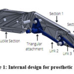 |
Figure 1: Internal design for prosthetic finger |
The bionic hand’s fingers needed to have three sections and the same kind of movement as a human hand in order to function like one. Linkages were used to join three distinct finger sections. Since it was difficult to connect all the sections in the original design [60], the pin locations were altered slightly. The pins were used to connect links in that location. To illustrate, the finger depicted in Figure 1 was used. Through the opening at one end, the triangular portion (Fig. 2) was fastened to the initial segment. A link was used to connect one of the extensions/pins to the worm gear, and the second section was linked to the pin that was the furthest from the next section.
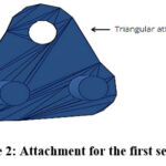 |
Figure 2: Attachment for the first section |
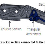 |
Figure 3: Knuckle section connected to the first section |
The first pin from the middle section connected to the final section of the finger. When the worm gear pulled the first link towards itself, the triangular section (Fig. 3) rotated and pulled the second link, subsequently moving the second section. This motion generated clockwise rotation of the third section.
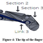 |
Figure 4: The tip of the finger |
The actual finger, depicted in Figure 4, was connected to the palm, with the third section linked to a knuckle section featuring a hole. The knuckle was secured to the backplate using screws.
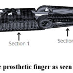 |
Figure 5: The prosthetic finger as seen from below |
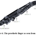 |
Figure 6: The prosthetic finger as seen from above |
The finger link at the beginning of the finger would be connected to a worm gear [61] that drives it, employing a mechanism similar to the gripper mechanism depicted in Figure 7. A significant advantage of utilizing a worm gear is that the hand remains locked in any position unless the user intends to move it. Additionally, worm gears are low maintenance and are employed in situations requiring a low gear ratio, resulting in increased torque.
Table 1: Required dimensions for the worm gear
|
Worm |
48 pitch, 3/16” bore, 5/16” outer diameter |
|
Gear |
24 gear, brass, 3/16” bore |
Design of Prosthetic Gripper
Figure 7 illustrates the design for the gripper [62], employing a similar working principle to actuate the finger. The gripper utilizes a worm gear consisting of two parts: a worm or screw, and a gear. The motor rotates the worm, which in turn rotates the gear inserted inside the grooves of the worm. A potentiometer can be affixed to the gear to measure its rotation and thereby determine the angle of the gripper. The same model of motor used for the elbow can also be employed for the gripper.
Table 2: Target values for the gripper
|
Opening span |
100mm |
|
Speed |
110mm/s |
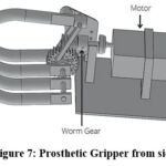 |
Figure 7: Prosthetic Gripper from side |
C. Design of Prosthetic Wrist
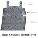 |
Figure 8: Complete prosthetic wrist |
The prosthetic wrist has been designed to rotate along the axis of the forearm, mimicking the pronation-supination movement. The smaller gear is connected to the motor and serves as the driver gear, while the larger gear is linked to the wrist and facilitates wrist rotation. An enhancement to this design could involve connecting the outer side of the wrist to a ball bearing to reduce friction during motion.
Table 3: Design specifications for the wrist.
|
Mass |
<100 g |
|
Speed |
≥1.42 rad/s (13.5 rpm) |
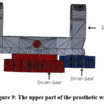 |
Figure 9: The upper part of the prosthetic wrist |
Design of Prosthetic Elbow
The moving components in the artificial elbow design of63 were unsuitable for amputees who might have larger stumps. A gear system was required to lift the arm with a single servo 164,65. While the arm could produce more torque (turning force) with gears, it came at the expense of speed. To drive a larger gear section attached to the forearm, a small gear was pressed onto the bicep servo. The designed gear system61 increased the torque from the servo by a factor of 2.10. This elbow has been designed to provide 110 degrees of rotation, allowing for both a straight orientation and a right-angle bend. With the addition of the gears, the servo now has to rotate the small gear by 290 degrees to completely bend the elbow. As previously mentioned, a standard servo can only rotate through 180 degrees, so modifications have to be made to increase the servo’s rotational range. One potential solution would be to remove the potentiometer from the motor and attach it to the driven gear. Thus, the potentiometer would rotate as the driven gear rotates and not the driver gear.
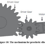 |
Figure 10: The mechanism for prosthetic elbow |
Conclusion
In this paper, sections of a prosthetic arm, such as the hand, wrist, and elbow, were reviewed. Each paper 16-59 was summarized based on the problem statement and the designs developed to address those issues. Next, two prosthetic hand variations were created per the design specifications, drawing inspiration from a variety of designs found in the literature review and other sources. It’s possible to 3D print the entire bionic arm, and the gripper can be machined. Electronic parts such as motors can be purchased off the shelf. The two variations of prosthetic arms, discussed in this paper can be controlled by the motors and perform movement of the prosthetic limb. EEG signals generated by central nervous system and EMG signals acquired at the intact muscles, duly classified for performing intended activity can be used to generate control signal for the motors.
Acknowledgement
Authors would like to thank AICTE, New Delhi, India and Vishwakarma Institute technology, Pune for the support and motivation.
Conflict of Interest
The authors declare that there are no conflicts of interests.
Funding Sources
This work is carried under the support received from AICTE, New Delhi, India under File no. 8-53/FDC/RPS (POLICY-I)/2019-20).
References
- “Grasping the Importance of Our Hands” Accessed on:Sep,22.2021. [Online]. Available: https://orthop.washington.edu/sit es/default/files/files/16-6-document.pdf
- “Limb Loss”. Accessed on: Sep. 25, 2021. [Online]. Available:https://medlineplus.gov/limbloss.html
- “Phantom pain”. Accessed on: Sep. 28, 2021. [Online]. Available:https://www.mayoclinic.org/diseases-conditions/phant om-pain/symptoms-causes/syc-20376272
- “Some Problems in the Management of Upper Extrem- ity Amputees”. Accessed on: Oct. 2, 2021. [Online]. Available:http ://www.oandplibrary.org/al/1955_02_036.asp
- “How do hands work?” Accessed on: Sep. 5, 2021. [O- nline].Available:https://www.ncbi.nlm.nih.gov/books/NBK279362/
- “Reasons for amputating”. Accessed on: Oct. 11, 2021.[Online].Available:https://www.ottobock.africa/en/your-individual-fitti ng/lower-limb/info-for-lower-limb-amputees/before-the-amputation/amputation-causes/
- “Prosthetics designers harness AI to assist India’s amp- utees”. Accessed on: Sep. 19, 2021. [Online]. Available: https://ww w.scidev.net/global/features/prosthetics-designer s-harness-ai-to-assist-india-s-amputees/
- “Frostbite”. Accessed on: Oct. 12, 2021. [Online]. Available:https://orthoinfo.aaos.org/en/diseases–conditions /frostbite/
- “Bone cancer”. Accessed on: Oct. 11, 2021. [Online]. Available:https://www.macmillan.org.uk/cancer-informa-tion-and -support/bone-cancer
- “Arm & Hand Prosthetics: The complete guide from the prosthetic experts at MCOP”. Accessed on: Sep. 8, 2021. [Onli- ne].Available:https://mcopro.com/blog/resources/arm-hand-prosthetics/
- “Passive prosthetic hands and tools: A literature review”. Accessed on: Oct. 12, 2021. [Online].Available: https:// www. ncbi.nlm.nih.gov/pmc/articles/PMC5810914/
- “Body-powered upper limb prostheses”. Accessed on: Oct.13,2021. [Online].Available:https://www.ottobock.in/artific ial-limbs/upper-limb/solution-overview/body-powered-upper-limb-prosthesis/
- Godfrey SB, Piazza C, Felici F, Grioli G, Bicchi A and Catalano MG (2021) Usability Assessment of Body Controlled Electric Hand Prostheses: A Pilot Study. Front. Neurorobot. 15:683253. doi: 10.3389/fnbot.2021.683253
CrossRef - “Limb Loss Stats” Accessed on: Sep 7.2021. [Online]. Available: https://u.osu.edu/fitness4all/loss-limb-stats/
- Millstein, S., Heger, H., and Hunter, G. (1986). Prosth- etic use in adult upper limb amputees: a comparison of the body powered and electrically powered prostheses. Prosth- et. Orthot. Int. 10, 27–34.doi:10.3109/03093648609103076
CrossRef - J. Fajardo, V. Ferman, D. Cardona, G. Maldonado, A. Lemus and E. Rohmer, “Galileo Hand: An Anthropomorphic and Affordable Upper-Limb Prosthesis,” in IEEE Access, vol. 8, pp. 81365-81377, 2020, doi: 10.1109/AC CESS.2020.2990881.
CrossRef - X. Jing, X. Yong, Y. Jiang, H. Yokoi and R. Kato, “A low-degree of freedom EMG prosthetic hand with nails and sprin- gs to improve grasp ability,” 2014 7th International Conference on Biomedical Engineering and Informatics, 2014, pp. 562-567, doi: 10.1109/BMEI.2014.7002837.
CrossRef - Tatsuro NAGAO, M.D, “Analysis of Normal Finger Functions in Activities of Daily Life,” Rehabilitation Center, Kyushu Rosai Hospital, Kita Kyushu City, Japan, 1971.
- M. Yoshikawa, R. Sato, T. Higashihara, T. Ogasawara and N. Kawashima, “Rehand: Realistic electric prosthetic hand created with a 3D printer,” 2015 37th Annual Interna- tional Conference of the IEEE Engineering in Medicine and Biology Society (EMBC), 2015, pp. 2470-2473, doi: 10.1109/EMBC.2015.7318894.
CrossRef - C. Metcalf, “Southampton hand assessment procedure (SHAP),” http://www.shap.ecs.soton.ac.uk, 2015.
- A. Atasoy, E. Kaya, E. Toptas, S. Kuchimov, E. Kaplanoglu and M. Ozkan, “24 DOF EMG controlled hybrid actuated prosthetic hand,” 2016 38th Annual Internation- al Conference of the IEEE Engineering in Medicine and Biology Society (EMBC), 2016, pp. 5059-5062, doi: 10.110 9/EMBC.2016.7591864.
CrossRef - L. Liow, A. B. Clark and N. Rojas, “OLYMPIC: A Modular, Tendon-Driven Prosthetic Hand With Novel Finger and Wrist Coupling Mechanisms,” in IEEE Robotics and Automation Letters, vol. 5, no. 2, pp. 299-306, April 2020, doi: 10.1109/LRA.20 19.2956636.
CrossRef - B. Calli, A. Singh, A. Walsman, S. Srinivasa, P. Abbe- el and A. M. Dollar, “The YCB object and Model set: Towards common benchmarks for manipulation research,” 2015 International Conference on Advanced Robotics (ICAR), 2015, pp. 510-517, doi: 10.1109/ICAR.2015.7251504.
CrossRef - R. Fourie and R. Stopforth, “The mechanical design of a biologically inspired prosthetic hand, the touch hand 3,” 2017 Pattern Recognition Association of South Africa and Robotics and Mechatronics (PRASA-RobMech), 2017, pp. 38-43, doi: 10.1109/RoboMech.2017.8261120.
CrossRef - Raymond M.A; Dollar; (2017); Yale Open hand Project; IEEE Spectrum Robotics and Automation Magazine, Vol. 24, No.1 March 2017, pgs
- T. Lenzi, J. Lipsey and J. W. Sensinger, “The RIC Arm —A Small Anthropomorphic Transhumeral Prosthesis,” in IEEE/ASME Transactions on Mechatronics, vol. 21, no. 6, pp. 2660-2671, Dec. 2016, doi: 10.1109/TMEC H.2016.259 6104.
CrossRef - N. E. Krausz, R. A. L. Rorrer and R. F. f. Weir, “Desi- gn and Fabrication of a Six Degree-of-Freedom Open Sour- ce Hand,” in IEEE Transactions on Neural Systems and Rehabilitation Engineering, vol. 24, no. 5, pp. 562-572, May 2016, doi: 10.1109/TNSRE.2015.2440177.
CrossRef - “Open Source Hand: A 6 Degree-Of-Freedom Open Source Prosthetic Hand”. Accessed on: Oct 24, 2021. [Online]. Available:https:// opensourcehand.wordpress.com/
- Biddiss, Elaine A., and Tom T. Chau. “Upper limb prosthesis use and abandonment: A survey of the last 25 years.” Prosthetics and orthotics international 31.3 (2007): 236-257.
CrossRef - P. Wattanasiri, P. Tangpornprasert and C. Virulsri, “De- sign of Multi-Grip Patterns Prosthetic Hand With Single Actuator,” in IEEE Transactions on Neural Systems and Rehabilitation Engineering, vol. 26, no. 6, pp. 1188-1198, June 2018, doi: 10.1109/ TNSRE.2018.2829152.
- Medynski, Courtney and Bruce Rattray. “Bebionic Prosthetic Design.” (2011).
- Controzzi, Marco; Clemente, Francesco; Barone, Diego; Ghionzoli, Alessio; Cipriani, Christian (2016). The SSSA-MyHand: a dexterous lightweight myoelectric hand prosthesis. IEEE Transactions on Neural Systems and Rehabilitation Engineering ,() ,1–1.doi:10.1109/tnsre.2016 .2578980
- D. A. Bennett, S. A. Dalley, D. Truex and M. Goldfarb, “A Multigrasp Hand Prosthesis for Providing Precision and Conformal Grasps,” in IEEE/ASME Trans- actions on Mechatronics, vol. 20, no. 4, pp. 1697-1704, Aug. 2015, doi: 10.1109/ TMECH. 2014. 234 9855.
CrossRef - Y. Cho, Y. Lee, P. Kim, S. Jeong and K. -S. Kim, “The MSC Prosthetic Hand: Rapid, Powerful, and Intuitive,” in IEEE Robotics and Automation Letters, doi: 10.1109/ LRA .2022.3140444.
- M. H. Chang et al., “Anthropomorphic Prosthetic Hand Inspired by Efficient Swing Mechanics for Sports Activities,” in IEEE/ASME Transactions on Mechatronics, doi: 10.1109/TMECH.2021.3084311.
CrossRef - T. Takaki and T. Omata, “High-Performance Anthropomorphic Robot Hand With Grasping-Force-Magnificat- ion Mechanism,” in IEEE/ASME Transactions on Mechatronics, vol. 16, no. 3, pp. 583-591, June 2011, doi: 10.1109/TMEC H.2010.2047866.
CrossRef - N. Kim, S. Yun and D. Shin, “A Bioinspired Lightwe- ight Wrist for High-DoF Robotic Prosthetic Arms,” in IEEE/ASME Transactions on Mechatronics, vol. 24, no. 6, pp. 2674-2683, Dec. 2019, doi: 10.1109/TMECH.2019.294 1279.
CrossRef - J. Fras, M. Macias, F. Czubaczynski, P. Salek, and J. Glowka. Soft flexible gripper design, characterization and application. In International Conference SCIT, Warsaw, Poland. Springer, 2016
CrossRef - G. Lee, G. Y. Hong and Y. Choi, “Tendon-Driven Compliant Prosthetic Wrist Consisting of Three Rows Based on the Concept of Tensegrity Structure,” in IEEE Robotics and Automation Letters, vol. 6, no. 2, pp. 3956 -3963, April 2021, doi: 10.1109/LRA.2021.3067237.
CrossRef - S. Kim, H. In, J. Song, and K. Cho, “Force characteristics of rolling contact joint for compact structure,” in Proc. IEEE Int. Conf. Biomed. Robot. Biomechatronics, pp. 1207–1212, 2016.
CrossRef - Y. Kim, “Anthropomorphic low-inertia high-stiffness manipulator for high-speed safe interaction,” IEEE Trans. Robot., vol. 33, no. 6, pp. 1358–1374, Dec. 2017.
CrossRef - “COMPLIANT MECHANISMS EXPLAINED” Aug. 15, 2014. Accessed on: Oct 25, 2016. [Online]. Available: https://www.compliantmechanisms .byu.edu/about-compliant-mechanisms
- F. Montagnani, M. Controzzi and C. Cipriani, “Prelim- inary design and development of a two degrees of freedom passive compliant prosthetic wrist with switchable stiffness” 2013 IEEE International Conference on Robotics and Biomimetics (ROB IO), 2013, pp. 310-315, doi: 10.1109/ROBIO.2013.6739477.
CrossRef - Motion Control, Inc. 115 N. Wright Brothers Drive, Salt Lake City.
CrossRef - N. Kim, S. Yun and D. Shin, “A Bioinspired Ligh- ight Wrist for High-DoF Robotic Prosthetic Arms,” in IEEE/ASME Transactions on Mechatronics, vol. 24, no. 6, pp. 2674-2683, Dec. 2019, doi: 10.1109/TMECH.2019.294 1279.
CrossRef - S. L. Delp, F. C. Anderson, A. S. Arnold, P. Loan, A. Habib, C. T. John, E. Guendelman, and D. G. Thelen, “Opensim: open-source software to create and analyze dynamic simulations of movement,” IEEE transactions on biomedical engineering, vol. 54, no. 11, pp. 1940–1950,2007. UT, 84116, USA
CrossRef - Bennett DA, Mitchell J, Goldfarb M. Design and characterization of a powered elbow prosthesis. Annu Int Conf IEEE Eng Med Biol Soc. 2015; 2015:2458-61. doi: 10.1109/EMBC.2015.7318891. PMID: 26736791
CrossRef - Ten Kate J, Smit G, Breedveld P. 3D-printed upper limb prostheses: a review. Disabil Rehabil Assist Technol. 2017;12(3):300-314. doi:10.1080/17483107.2016.1253117
CrossRef - Resnik L, Klinger SL, Etter K. The DEKA Arm: its features, functionality, and evolution during the Veterans Affairs Study to optimize the DEKA Arm. Prosthet Orthot Int. 2014;38(6):492-504. doi:10.1177/0309364613506913
CrossRef - Dunai L, Novak M, García Espert C. Human Hand Anatomy-Based Prosthetic Hand. Sensors (Basel). 2020;21(1):137. Published 2020 Dec 28. doi:10.3390/s21010137
CrossRef - Ju N, Lee KH, Kim MO, Choi Y. A User-Driven Approach to Prosthetic Upper Limb Development in Korea. Healthcare (Basel). 2021;9(7):839. Published 2021 Jul 2. doi:10.3390/healthcare9070839
CrossRef - 1. Fascinated. with Michelangelo®. Accessed February 19, 2024. https://accessprosthetics.com/wp-content/uploads/2017/06/ michelangelo-technology.pdf.
- Mohammadi A, Lavranos J, Tan Y, Choong P, Oetomo D. A Paediatric 3D-Printed Soft Robotic Hand Prosthesis for Children with Upper Limb Loss. Annu Int Conf IEEE Eng Med Biol Soc. 2020;2020:3310-3313. doi:10.1109/EMBC44109.2020.9176848
CrossRef - Andrianesis, K., & Tzes, A. (2015). Development and control of a multifunctional prosthetic hand with shape memory alloy actuators. J Intell Robot Syst, 78(257), 289. doi: https://doi.org/10.1007/s10846-014-0061-6
CrossRef - Imran A, Escobar W, Barez F. Design of an Affordable Prosthetic Arm Equipped With Deep Learning Vision-Based Manipulation. Volume 6: Design, Systems, and Complexity. Published online November 1, 2021. doi:10.1115/imece2021-68714
CrossRef - Shin YJ, Kim S, Kim K-S. Design of prosthetic robot hand with high performances based on novel Actuation Principles. IFAC Proceedings Volumes. 2013;46(5):313-318. doi:10.3182/20130410-3-cn-2034.00111
CrossRef - Xu, Z., & Todorov, E. (2016). Design of a highly biomimetic anthropomorphic robotic hand towards artificial limb regeneration. In 2016 IEEE International Conference on Robotics and Automation (ICRA) (pp. 3485-3492). IEEE. doi:10.1109/ICRA.2016.7487528
CrossRef - Weiner P, Starke J, Rader S, Hundhausen F, Asfour T. Designing Prosthetic Hands With Embodied Intelligence: The KIT Prosthetic Hands. Front Neurorobot. 2022;16:815716. Published 2022 Mar 10. doi:10.3389/fnbot.2022.815716
CrossRef - Bennett DA, Dalley SA, Goldfarb M. Design of a hand prosthesis with precision and conformal grasp capability. Annu Int Conf IEEE Eng Med Biol Soc. 2012;2012:3044-3047. doi:10.1109/EMBC.2012.6346606
CrossRef - “DARA Robot Fingers – InMoov updated fingers”. Accessed on: Oct. 30, 2021. [Online].Available: https://ww w.thingiverse .com/thing:2551671#How%20I%20Designed%20This
- “Worm Gear”.Accessed on: Nov.27, 2021. [Online]. Available: https://grabcad.com/library/worm-gear-1
- “Robotic 3 hand with worm gear and servo 360°”. Accessed on: Oct. 30, 2021. [Online].Available: https://gra- bcad.com /library/robotic-3-hand-with-worm-gear-and-servo-360-1
- “Hand and Forarm”. Accessed on: Nov. 23, 2021. [Online]. Available: https://inmoov.fr/hand-and-forarm/
- “Low Cost Myoelectric Prosthetic Arm”. Accessed on: Nov. 13, 2021.[Online]. Available:https://mdesigns.space/projects/ project-three-2jhsa
- “Prosthetic Arm”. Accessed on: Nov. 26, 2021. [Online].Available: https://grabcad. com/library/prosthetic-arm-14 e-prints, pp. arXiv– 1811, 2018.

