
Manuscript accepted on :
Published online on: 02-12-2015
Plagiarism Check: Yes
D. M Mikhaylov , Т. R Khabibullin, A. F Shayakov, A. A Shinkarenko, D. A Andryakov, I. A Ovchinnikov, R. O Roslavtsev
National Research Nuclear University MEPhI (Moscow Engineering Physics Institute), Kashirskoe highway 31, 115409, Moscow, Russian Federation
DOI : https://dx.doi.org/10.13005/bpj/858
Abstract
Practically many of the exiting wireless endoscopic capsules cannot be controlled from the outside and move in the organs with the help of peristaltic motions. The developed magnetic control system for wireless endoscopic capsule helps to solve this problem. The system consists of six identical solenoids situated on the faces of the cube. There are seven schemes of powering the coils. Calculations for each scheme to evaluate magnetic field and power induction vectors were made. Demands for distribution of magnetic field, which is generated by the system, and parameters of field force interaction with diagnostics capsule with different variants of magnetic system coils powering were set. For illustrative purposes calculation diagrams are presented.
Keywords
magnet system configuration; coils power supply scheme; distribution of magnet induction vector and force
Download this article as:| Copy the following to cite this article: Mikhaylov D. М, Khabibullin Т. R, Shayakov А. F, Shinkarenko А. А, Andryakov D. А, Ovchinnikov I. А, Roslavtsev R. О. Magnet System Configuration for Wireless Endoscopic Capsule. Biomed Pharmacol J 2015;8(1) |
| Copy the following to cite this URL: Mikhaylov D. М, Khabibullin Т. R, Shayakov А. F, Shinkarenko А. А, Andryakov D. А, Ovchinnikov I. А, Roslavtsev R. О. Magnet System Configuration for Wireless Endoscopic Capsule. Biomed Pharmacol J 2015;8(1). Available from: http://biomedpharmajournal.org/?p=1988 |
Introduction
The wireless capsule endoscopy now plays an important role in digestive tract examination as it provides its comfortable and detailed diagnostics. It allows finding timely abnormalities, continuing more detailed examination and treatment. [1-4]
Nowadays, a lot of attention is paid to creation of magnet control systems for wireless endoscopic capsules, because with the help of the following technology it is possible to:
- stop, rotate and move endoscopic capsule in the digestive system for more detailed analysis during the procedure (standard capsule can be stuck and, for example, stay in the stomach for a long time);
- provide speed delivery of the endoscopic capsule to the dodecadactylon of the patients who are under risk of long-lasting stay of capsule in the upper part of the intestinal tract;
- make online screening of stomach walls and small bowel at the same time. [5-7]
Many authors discussed the following topic. For example, magnet control system of Siemens and Olympus endoscopic capsule has a new method of magnet directing, information system, image processing system and endoscopic capsule. During examination patient is placed so that his stomach with the capsule is in the middle of the artificial magnetic field. Magnet generates different magnetic fields. Therefore, doctor can control the capsule with the help of joystick. [8]
Kim et al. present modified magnetic endoscopic capsule, which can be fixed in the stomach and can control stomach movement function. [9] Lien et al. proposed their own magnet control system for endoscopic capsule in [10]. Sun et al. describe multi-use of magnetic control system for an endoscopic capsule [11]. Wakefield speaks about magnetmovable endoscopic capsule, which provides medical expertise and treatment of digestive system, reproductive tracts, tracheae, lungs and vascular system [12].
Usually a capsule complex control system is based on magnet coils system, which generate magnetic field to move the capsule in the necessary direction and in case of need to make distance recharge of power element within the capsule. Accuracy and capsule movement speed depends on magnet parameters. That is why the main attention should be paid to magnet system configuration.
In the present article modeling and magnetic field induction vectors and force are presented, which affect diagnostics capsule and calculations diagrams are shown for each powered scheme. Calculations for the prototype of the developed magnet system are also provided.
Materials and methods
Let us consider magnet system configuration for which numerical calculation was made. The system consists of six identical coils (solenoids) placed on the cube faces (origin of coordinates is situated in the center of the cube). The coil system is described in details in article [13].
The following coil parameters were used for calculation:
- Inner diameter – 200 mm;
- Outer diameter – 300 mm;
- Coil spread – 30 mm;
- Number of turns in the coil – 1500;
- Current, which flows through powered coil – 1А.
When wrapping solenoids, copper wire should be protected with glass-cloth from solenoid surface frame. Copper wire ends should be additionally protected with double course of cambric isolation.
Coil geometrical location used for calculations is presented in Figures 1 and 2.
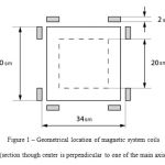 |
Figure: 1 – Geometrical location of magnetic system coils (section though center is perpendicular to one of the main axis) |
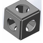 |
Figure: 2 – Schematic layout of magnetic system coils |
Calculations were made for seven schemes of coil powering presented in Figure 3 and in Table 1.
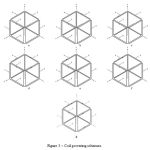 |
Figure: 3 – Coil powering schemes |
a – Scheme 1, only coil 1 is powered, other coils are not powered.
b – Scheme 2, coils 1 and 2 are powered, other coils are not powered.
c – Scheme 3, coils 1 and 4 are powered, other coils are not powered.
d – Scheme 4, coils 1, 2, 3, 4 are powered, other coils are not powered.
e – Scheme 5, coils 1 and 4 are powered, other coils are not powered.
f – Scheme 6, coils 1, 4, 5 are powered, other coils are not powered.
g – Scheme 7, all coils are powered.
Table 1 – Scheme of switching on (powering) magnetic system coils for calculation.
| Scheme number | Coil 1 | Coil 2 | Coil 3 | Coil 4 | Coil 5 | Coil 6 |
| 1 | + | – | – | – | – | – |
| 2 | + | + | – | – | – | – |
| 3 | + | – | – | + | – | – |
| 4 | + | + | + | + | – | – |
| 5 | + | – | – | +
(current direction in coil 4 is opposite to current direction in coil 4 for scheme 3) |
– | – |
| 6 | + | – | – | + | + | – |
| 7 | + | + | + | + | + | + |
For each of presented in Scheme 1 magnetic system powering schemes х, у and z induction vectors were calculated for magnetic field (Bx, By, Bz) and force (Fx, Fy, Fz) [14], which affect diagnostics capsule (it is suggested, that force affects capsule, presented in the form of magnetic dipole with parameters 1A*m2, oriented in the calculated point along power line of magnetic field, which flows through this point), in cube with face 200 mm and step equal to 20 mm along the main coordinate axis for 6 plains with coordinates:
- z = 0;
- z = -100 mm;
- z = 100 mm;
- y = 0;
- y = -100 mm;
- y = 100 mm.
Calculation was made with finite-element method [15] with the help of ANSYSMaxwell program for static mode. Net in the working area, i.e. within the cube with parameters 200×200×200 mm, was set with maximum element size equal to 10 mm. Error value was 1%. Calculation was made within the area 1140×1140×1140 mm with “Balloon” type boundary conditions, which means tangential and normal component of vector potential turn into zero at infinity.
Results
Calculation results for switching Scheme 1.
In Figure 4 calculation results for vector distribution of magnetic induction (purple arrows) and force (green arrows) in the plain (у,z) (x = 0) for switching scheme No.1 are shown. Analogue and vector distribution processes are evaluated for plains х = 100, х = -100, y = 0 (x,z) and у = 100. In other plains and vector distribution is equal. Therefore, the presented diagrams give the full picture of field and force distribution for the following coil switching method.
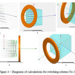 |
Figure: 4 – Diagrams of calculations for switching scheme No.1 |
a – Calculation results for magnetic induction vector and force distribution in the plain (у,z) (x = 0).
b – Calculation results for magnetic induction vector and force distribution in the plain x = 100.
c – Calculation results for magnetic induction vector and force distribution in the plain x = -100.
d – Calculation results for magnetic induction vector and force distribution in the plain y = 0 (x,z).
e – Calculation results for magnetic induction vector and force distribution in the plain y = 100.
Calculation results for switching Scheme 2.
Figure 5 provides calculation results for vector distribution of magnetic induction (purple arrows) and force (green arrows) in the plain (у,z) (x = 0) for switching scheme No. 2. Analogue and vector distribution processes are evaluated for plains х = 100, (z,x) (y = 0), у = 100. In other plains and vector distribution is equal; therefore the presented diagrams give the full picture of field and force distribution for the following coil switching method.
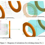 |
Figure 5: Diagrams of calculations for switching scheme No. 2 |
a – Calculation results for magnetic induction vector and force distribution in the plain (у,z) (x = 0).
b – Calculation results for magnetic induction vector and force distribution in the plain x = 100.
c – Calculation results for magnetic induction vector and force distribution in the plain (z,x) (y = 0).
d – Calculation results for magnetic induction vector and force distribution in the plain y = 100.
Calculation results for switching Scheme 3.
In Figure 6 calculation results for magnetic induction (purple arrows) and force (green arrows) vector distribution in the plain (у,z) (x = 0) for switching scheme No. 3 are presented. Analogue and vector distribution processes are evaluated for plains х = 100 mm, х = -100 mm, (z,x) (y = 0), у = 100 mm, у = -100 mm, (х,у) (z = 0), z = 100 mm. In plain z = -100 mm and distribution is equal to the distribution in plain z = 100 mm, therefore the presented diagrams give the full picture of field and force distribution for the following coil switching method.
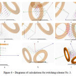 |
Figure 6: Diagrams of calculations for switching scheme No. 3 |
a – Calculation results for magnetic induction vector and force distribution in the plain (у,z) (x = 0).
b – Calculation results for magnetic induction vector and force distribution in the plain x = 100.
c – Calculation results for magnetic induction vector and force distribution in the plain x = -100.
d – Calculation results for magnetic induction vector and force distribution in the plain (z,x) (y = 0).
e – Calculation results for magnetic induction vector and force distribution in the plain у = 100.
f – Calculation results for magnetic induction vector and force distribution in the plain у = -100.
g – Calculation results for magnetic induction vector and force distribution in the plain (х,у) (z = 0).
h – Calculation results for magnetic induction vector and force distribution in the plain z = 100.
i – General three-dimensional distribution of and vectors.
Calculation results for switching Scheme 4.
Figure 7 shows results of calculations for vector distribution of magnetic induction (purple arrows) and force (green arrows) in the plain (х,z) (у = 0) for switching scheme No. 4. Analogue and vector distribution processes are evaluated for plains у = 100 mm, (х,y) (z = 0), z = 100 mm. In other plains and vector distribution is equal. The presented diagrams give the full picture of field and force distribution for the following coil switching method.
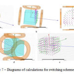 |
Figure 7: Diagrams of calculations for switching scheme No. 4 |
a – Calculation results for magnetic induction vector and force distribution in the plain (х,z) (у = 0).
b – Calculation results for magnetic induction vector and force distribution in the plain у = 100 mm.
c – Calculation results for magnetic induction vector and force distribution in the plain (х,y) (z = 0).
d – Calculation results for magnetic induction vector and force distribution in the plain z = 100 mm.
e – General three-dimensional distribution of and vectors.
Calculation results for switching Scheme 5.
In Figure 8 calculation results for vector distribution of magnetic induction (purple arrows) and force (green arrows) in the plain (y,z) (x = 0) for switching scheme No. 5 are presented. Analogue and vector distribution processes are evaluated for plains x = 100 mm, x = -100 mm, (х,z) (y = 0), y = 100 mm, y = -100 mm, (х,y) (z = 0), z = 100 mm. In other plains and vector distribution is equal; therefore the presented diagrams give the full picture of field and force distribution for the following coil switching method.
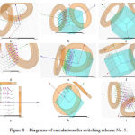 |
Figure 8 – Diagrams of calculations for switching scheme No. 5 |
a – Calculation results for magnetic induction vector and force distribution in the plain (у,z) (x = 0).
b – Calculation results for magnetic induction vector and force distribution in the plain x = 100.
c – Calculation results for magnetic induction vector and force distribution in the plain x = -100.
d – Calculation results for magnetic induction vector and force distribution in the plain (x,z) (y = 0).
e – Calculation results for magnetic induction vector and force distribution in the plain у = 100.
f – Calculation results for magnetic induction vector and force distribution in the plain у = -100.
g – Calculation results for magnetic induction vector and force distribution in the plain (х,у) (z = 0).
h – Calculation results for magnetic induction vector and force distribution in the plain z = 100.
i – General three-dimensional distribution of and vectors.
Calculation results for switching Scheme 6.
Figure 9 provides calculation results for magnetic induction (purple arrows) and force (green arrows) vector distribution in the plain (y,z) (x = 0) for switching scheme No. 6. Analogue and vector distribution processes are evaluated for plains x = 100 mm, x = -100 mm, (х,z) (y = 0), y = 100 mm, y = -100 mm, (х,y) (z = 0), z = 100 mm, z = -100 mm.
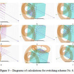 |
Figure 9: Diagrams of calculations for switching scheme No. 5 |
a – Calculation results for magnetic induction vector and force distribution in the plain (у,z) (x = 0).
b – Calculation results for magnetic induction vector and force distribution in the plain x = 100.
c – Calculation results for magnetic induction vector and force distribution in the plain x = -100.
d – Calculation results for magnetic induction vector and force distribution in the plain (x,z) (y = 0).
e – Calculation results for magnetic induction vector and force distribution in the plain y = 100 mm.
f – Результаты расчёта распределения вектора магнитной индукции и силы в плоскости y = -100.
g – Calculation results for magnetic induction vector and force distribution in the plain (х,у) (z = 0).
h – Calculation results for magnetic induction vector and force distribution in the plain z = 100.
i – Calculation results for magnetic induction vector and force distribution in the plain z = -100.
Calculation results for switching Scheme 7.
In Figure 10 calculation results are presented for vector distribution of magnetic induction (purple arrows) and force (green arrows) in the plain (х,y) (z = 0) for switching scheme No. 7. Analogue and vector distribution processes are evaluated for plain z = 100 mm. In other plains and vector distribution is equal; therefore the presented diagrams give the full picture of field and force distribution for the following coil switching method.
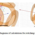 |
Figure 10: Diagrams of calculations for switching scheme No. 7 |
a – Calculation results for magnetic induction vector and force distribution in the plain (х,y) (z = 0).
b – Calculation results for magnetic induction vector and force distribution in the plain z = 100.
Conclusions
Therefore, in the present article requirements to magnetic field distribution are presented. The field is generated by the system and parameters of force interaction with the diagnostics capsule for different variants of magnet system coil switching. The received numerical data are presented in the form of diagrams of field and force distribution, which affect magnetic capsule modeled in the form of magnetic dipole along the magnetic field vector destination.
The chosen configuration of the magnet system (coils, which make a cube with its faces) helps to create field distribution in space with configuration, which gives an opportunity to orient capsule axis (magnetic dipole) in space in the necessary direction through field vector orientation in the given space point and capsule rotation after magnetic field direction. Magnetic field gradient, created by the coils, forms ponderomotive force distribution, which allow moving the capsule in the specified direction.
Thus, the modeled magnetic system can provide rotation and movement of the capsule in space by changing outer field gradient, created by the magnetic coils.
Magnetic system configuration calculations will be used for further calculations and experiments for providing control over diagnostics endoscopic capsule with the help of magnetic field.
Acknowledgement
The publication is prepared in accordance with the scientific research under the Agreement between “Mobile informatics” (LLC) and Ministry of Education and Science of the Russian Federation No. 14.579.21.0053 dated 23.09.2014. Unique project identification number is RFMEFI57914X0053.
References
- de Francis, B.S. Lewis, D.S. Mishkin. Capsule endoscopy in understandable language / trans. from English. Ed. E.D. Fedorov, E.V. Ivanova. – M: Practical medicine, 2012. – 128 p.: Ills.
- Mikhaylov Dmitry, Zhukov Igor, Konev Vladimir, Starikovskiy Andrey, Khabibullin Timur, Tolstaya Anastasia, Kukushkin Alexander. Review of features and metafeatures allowing recognition of abnormalities in the images of GIT. 17th IEEE Mediterranean Electrotechnical Conference (MELECON), 2014. 13-16 April 2014. Pages: 231 – 235.
- Baopu Li, Meng, M.Q.-H. Tumor Recognition in Wireless Capsule Endoscopy Images Using Textural Features and SVM-Based Feature Selection. Information Technology in Biomedicine, IEEE Transactions (Volume: 16, Issue: 3), May 2012.
- Dmitry Mikhaylov, Andrey Starikovskiy, Vladimir Konev, Andrey Grigorenko, Larisa Shustova. Review of software for automated analysis of digestive tract images. Biosciences Biotechnology Research Asia, December 2014. Vol. 11(3), p. 1109-1114.
- Francis M Creighton Iv. Rotating and pivoting magnet for magnetic navigation. Patent WO 2003083880 A1, pub. date 9 Oct 2003.
- Sehyuk Yim, Sitti, M. Design and analysis of a magnetically actuated and compliant capsule endoscope robot. IEEE International Conference on Robotics and Automation (ICRA), 2011. Pages: 4810 – 4815.
- Stefan Förtsch, Aleksandar Juloski, Henrik Keller, Philip Mewes, Dominik Neumann. Verfahren und einrichtung zur untersuchung eines hohlorgans mit einer magnetgeführten endoskopkapsel. Patent WO 2012110324 A1, pub. date 23 Aug 2012.
- Jean-Francois Rey, H. Ogata, N. Hosoe, K. Ohtsuka, N. Ogata, K. Ikeda, H. Aihara, I. Pangtay, T. Hibi, S. Kudo, H. Tajiri “Feasibility of stomach exploration with a guided capsule endoscope“, Endoscopy 2010
- Kim, H.M., Choi, J.S., Cho, J.H. A pilot trial of ambulatory monitoring of gastric motility using a modified magnetic capsule endoscope. Journal of Neurogastroenterology and Motility, Volume 20, Issue 2, 2014, Pages 261-264.
- Gi-Shih Lien, Chih-Wen Liu, Joe-Air Jiang, Cheng-Long Chuang, Yu-Hao Chang, Wen-Chi Huang. Capsule endoscope magnetic control system. Patent application: US 20150087898 A1, publication date Mar 26, 2015.
- Sun, Z.-J., Cheng, X.-G., Cao, S., Ye, B., Zhang, H.-H., Liu, S. Multi-applications of a magnet configuration in actuating capsule endoscope. IEEE/ASME International Conference on Advanced Intelligent Mechatronics, 2014. Pages 106-111.
- Wakefield Glenn. Magnetically propelled capsule endoscopy. Patent application: WO 2004086958 A1, publication date Oct 14, 2004.
- Khabibullin Timur, Anpilogov Artem, Shayakov Askar, Konev Vladimir, Lebedev Grigoriy, Tolstaya Anastasia, Shinkarenko Anton. Magnetically based hardware-software complex for wireless endoscope capsule control. Biosciences Biotechnology Research Asia. 2015. Vol. 12(2).
- Saveliev I.V. General physics course. Т.2. Electricity and magnetism. Waves. Optics. 2nd, reworked. – М.: Nauka, Chief-ed. Phys. And math. Lit., 1982. – 496 p.
- Gallager R. Finite elements method. Basics: Transl. from Eng. – М.: Mir, 1984.

