
Manuscript accepted on :
Published online on: 23-11-2015
Plagiarism Check: Yes
R. Harrish Madhan and Kavi Priya
Electronic and Communication Engineering Sathyabama University Chennai, Tamil Nadu
DOI : https://dx.doi.org/10.13005/bpj/612
Abstract
This is an electronic system that allows the vehicle to slow while approaching another vehicle and accelerate again to the preset speed when traffic is cleared. It also warns the driver or applies brake if there is a high risk of a collision. In this project we are going to develop the micro controller based automatic vehicle speed control system. Now-a-days we can see that more number of accidents happens in highways. Most of the reason for accident is driver mistake. To avoid this situation we make the system which is called adaptive cruise control system. This system consist of Ultra sonic based obstacle detector, whenever it detect the obstacle automatically speed will be reduced, when the distance of the obstacle increases automatically speed gets increased. In this system, driver no needs to give the acceleration and also break, which is entirely controlled by system. Existing system is semi automatic and this system will be a fully automatic system.
Keywords
cruise; collision; preset speed; obstacle
Download this article as:| Copy the following to cite this article: Madhan R. H, Priya K. Fully Automated Cruise Control System Using Ultrasonic Sensor. Biomed Pharmacol J 2015;8(1) |
| Copy the following to cite this URL: Madhan R. H, Priya K. Fully Automated Cruise Control System Using Ultrasonic Sensor. Biomed Pharmacol J 2015;8(1). Available from: http://biomedpharmajournal.org/?p=1351 |
Introduction
A cruise control system is one most commonly used system in our day-to-day life. This system is known to be in different names like Adaptive cruise control system, Conventional cruise control system, Automatic Cruise control system, speed control system,etc., these systems are mostly used in luxury vehicles like imported and high end cars. This system is used to avoid accidents that happens in highways, in most of the conditions accidents happens due to drivers behavior, in order to over come such situations we go for a system which is called as cruise control system. In many imported model cars their exists the cruise control system but they are not fully automatic, they are exclusively semi automatic, this mode is activated only after attaining a preset speed in case break or accelerator is applied the mode normally deactivates and it turns to manual. In this project the system is going to be a Fully Automatic Cruise Control System. ACC keeps the vehicle at a constant speed. If a car with ACC detects a slower moving vehicle ahead, then the vehicle automatically slows down and then follows the slow moving vehicle at a set distance. Once the road ahead is cleared, again the ACC accelerates the car to the previous speed. In the existing models the manufacturers use a Radioactive sensors and this causes many issues both technical and non-technical. Now we go for an ultrasonic sensor which has a very high frequency when compared to radioactive sensors. Ultrasonic sensors are capable of detecting obstacles at very far distance.
Fully Automatic Cruise Control
Automatic cruise control (ACC) is an intelligent form of cruise control that slows down and speeds up automatically, partial ACC only works at speeds of 20 or 25 mph. ACC works day and night, but its abilities are hampered by heavy rain, fog, or snow. Two companies are developing a more advanced cruise control that can automatically adjust a car’s speed to maintain a safe following distance. This new technology is called as automatic cruise control; a sensor is installed behind the grill of vehicle, to detect the speed and the distance of the vehicle ahead. Automatic cruise control is similar to conventional cruise control which maintains the vehicles preset speed. Like conventional cruise control, this system can automatically adjust the speed in order to maintain a proper distance between vehicles in different lane. This is achieved by an ultrasonic sensor. If the lead vehicle slows down, or if any another object detected, the system sends signal to the engine to decelerate. Once the road is clear, the system will re-accelerate the vehicle. Automatic Cruise Control (ACC) technology improves the function of standard cruise control by automatically adjusting the vehicles speed and distance to that of target vehicle. ACC uses a long range sensor to detect a target vehicle up to 20 meters in front and automatically adjusts the ACC vehicles speed and gap accordingly. Automatic Cruise Control decelerates or accelerates the vehicle according to the speed and distance settings established by the driver.
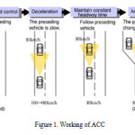 |
Figure 1: Working of ACC |
Enhancement IN ACC
The existing technologies provide, only a stop and go
Adaptive cruise control, which reduces the speed of the vehicle according to the speed of the vehicle in front. But the proposed system provides certain enhancements to the presently available adaptive cruise control system. When the ACC equipped vehicle detects a vehicle (in front) in the same lane it is traveling, initially the speed reduces and the sensors on the adjacent sides of the vehicle are engaged to check the adjacent lanes for any traffic movement. If the adjacent lane is unoccupied, the system automatically decides to steer the vehicle to the adjacent lane at an optimum speed without losing the stability of the vehicle and accelerates the car to the preset speed. After overtaking, which is decided by the input from the sensors on the adjacent side of the vehicle, it once again steers the car back to the previously occupied lane.
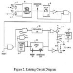 |
Figure 2: Existing Circuit Diagram |
In the proposed system we are going to use adaptive cruise control which will control the speed of the vehicle while approaching another vehicle. This is done using an ultrasonic sensor instead of using many other sensors. Pulse width modulation is used to control the speed of the vehicle automatically when a collision is going to occur. Using this system we can detect another vehicle even at a very far distance
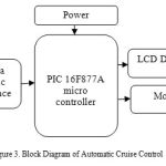 |
Figure 3: Block Diagram of Automatic Cruise Control |
Benefits of ACC
It is useful for long drives. This usually results in better fuel efficiency, reduction of accident rate for vehicles fitted with cruise control systems.
Drawbacks of ACC
The main problem regarding the normal Cruise Control technology is that it is not aware of other vehicle’s movement The driver must be always aware. One of the biggest challenges in designing ACC systems today are the costs associated. Auto manufacturers stress that advanced cruise control does not drive the car for you, and it cant be used in heavy traffic.
Hardware Implementation
Designing a prototype can explain the concept of automatic Cruise Control. This prototype is capable of detecting vehicle moving in front and can over take the vehicle after it is sensed. The prototype design consists of a pair of dc-geared motors, a sensor unit. The whole unit is movable with which it can also carry the target board with itself. The interfacing part must be done carefully to avoid impedance mismatching and logic level problems with the target board.
- Microcontroller: 8bit PIC microcontroller acts as the brain of the system.
- Display: LCD Display acting as the dashboard display for the driver to operate the system
- SONAR: ultrasonic distance sensor (dual) sense the front vehicle gap
- DC Motor: wheels are attached with this motor
- Switches: used to switch on the Automatic Cruise Control system by the driver.
Necessity of rtos
The need of having Real time operating systems is multitasking. The deadlines must be met with the time specified. The main purpose of real time vehicle tracking system is to have a timely update of tracking a vehicle. The current location co-ordinates, the speed and the direction of the vehicle must be updated from time to time. The proposed system is soft real time based system where the time deadlines will not lead to any harm or disaster. The basics features of the RTOS are explained below:
- RTOS kernel Codes are written mostly in C and its portable.
- Supports IPC (Inter Process Communication).
- Supports Message queue, Semaphore and Mutex.
Prototype Design
The prototype of the proposed system has certain in selecting the Target Board, Drive’s, Sensor’s and power supply design.
Sensors
Sensor works by transmitting a ultrasonic burst and providing a output pulse which corresponds to time required for the burst echo to return to sensor. By measuring the echo pulse width, distance of target can be easily calculated. Ultra sonic ranging module HC-SR04 provides 2cm – 400cm, the ranging accuracy reaches to 3mm. The module includes ultrasonic transmitter, receiver and a control circuit. The basic principle of the work:
- Using IO trigger for atleast 10us high level signal,
- Module automatically sends eight 40kHz and detect whether a pulse signal gets back.
- If the signal is back through high level time of high output IO duration is the time sending ultrasonic waves to return.
Table 1: Details of sensor
| Working Voltage | DC 5 V |
| Working Current | 15mA |
| Working Frequency | 40Hz |
| Max Range | 4m |
| MeasuringAngle | 15 degree |
| Trigger Input Signal | 10uS TTL pulse |
| Echo Output Signal | Input TTL level signal and the range in proportion |
| Dimension | 45*20*15mm |
Timing diagram
The Timing diagram is given below. We only need to supply short 10uS pulse to trigger input to start the ranging and the module will send an 8 cycle burst ultrasound at 40kHz and raise the echo. Echo is a distance object that pulse width and the range is in proportion. We can calculate the range through time interval between sending trigger signals and receiving echo signals. Formula: uS/58= cm or uS/148=inch or range=high level*velocity(340M/S)/2; using over 60ms measurement cycle, to prevent trigger signal to the echo signal.
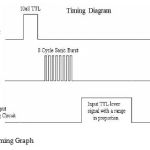 |
Figure 4: Timing Graph |
Communication Protocol
Sensor detects the objects by emitting short ultrasonic burst and then listening for echo. By the control of a host microcontroller (trigger pulse), a sensor emits a short 40 kHz burst. This burst travels by the air, and hits an object and then returns back to sensor. The sensor provides a output pulse to the host that would terminate if the echo is detected, hence the width of the pulse corresponds to the distance of the target.
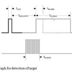 |
Figure 5: Graph for detection of target |
Object Positioning
Sensor can not accurately measure the distance of an object that: a) is more than three meters away, b) that has reflective surface at shallow angle so the sound will not be reflected back to the sensor, c) is too small to reflect back to the sensor.
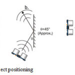 |
Figure 6: sensor object positioning |
Wave Propagation
In solid particle sound waves can propagate in four modes based on how the particles oscillate. Sound can propagate as longitudinal wave, shear wave, surface wave, and plate wave. Longitudinal and shear wave’s are two modes of propagation mostly used in ultrasonic testing. The particle movement is responsible for propagation of longitudinal and shear waves. Sensitivity and resolution are the two terms that is often used in ultrasonic inspection to locate flaws. Sensitivity is able to locate small discontinuities. Sensitivity increases with higher frequency (shorter wavelengths).
DC Motor
Whenever a robotics hobbyist talk about making a robot, the common thing comes to his mind is making the robot to move on the ground. There is always two options for the designer whether to use a DC motor or stepper motor. When it comes to speed, cost, weight, size… DC motors are always preferred than stepper motors. There are many things we can do with a DC motor when interfaced with microcontroller. For eg, you can control the speed of the motor, you can control the direction, you can encode the rotation made by DC motor.
Power Supply
The rectifier here used is a bridge rectifier. The bridge rectifier is used to converts AC to DC current and the DC motor is used to work based these rectifiers. A bridge rectifier over a conventional full-wave rectifier is that with a given transformer the bridge rectifier produces a voltage output that is nearly twice that of the conventional full-wave circuit. The voltage of 12v is given by the power supply unit to the controller. So now a battery is used to give the required power supply. A linear power supply is the oldest and simplest of power supply. In these power supply, electrical isolation can be provided by bulky line frequency transformers. The AC source can be rectified by a bridge rectifier to get a uncontrolled DC, and then the dc to dc converter can be used to get controlled dc output. Output voltage is regulated by dropping extra input voltage across a series transistor (also referred to as a series regulator). They have very small output ripples, theoreticaly zero noise, large hold-up time (typically 1–2 ms), and fastest response. The action of transformer is such that a time-varying (AC) voltage and current is transformed to higher or lower value, as set by a transformer turns ratio.
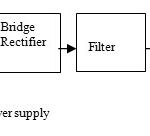 |
Figure 7: Linear power supply |
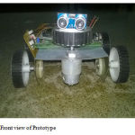 |
Figure 8: Front view of Prototype |
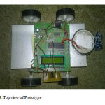 |
Figure 9: Top view of Prototype |
To avoid accidents happening in highways a prototype model using PIC16F877A micro controller has been developed. Whenever an obstacle is found then the speed of the vehicle is slowed down automatically. An LCD (Liquid Crystal Display) is fixed to the prototype displays the status message to the driver such as system ON, vehicle detected, vehicle stopped, speed of the vehicle, etc. This project aim is to avoid accidents happening in highways. In this prototype only the distance of the vehicle in multiple lanes are considered. Here a DC motor is used but in the case of vehicles, varying the air-fuel mixture in Internal Combustion (IC) engine the speed of the vehicle is adjusted to the desired level controls the fuel injector.
Despite the introduction of the system to market place, these are still in early days. The current system can measure up to 150m ahead of a car and reduces the cars speed if an obstacle appears. Whatever happens, the automobile market looks to explode. In 2002 there are not more than 100,000 vehicles equipped with ACC, but now it is set to reach eight million in 4 years, with Europe, South Asia, East Asia and the US. Around 17% of European built cars are likely to have ACC fitted as standard. Expansion is bounded to slow down, but by 2010 the market is 11.5 million units, some automakers use two radars — one for close range out to about 100 feet and a second that sees out to about 600 feet
References
- N.Wu, F. Chu, S. Mammar, andM. Zhou, “Petri net modeling of the cooperation behavior of a driver and a copilot in an advanced driving assistance system,” IEEE Trans. Intell. Transp. Syst., vol. 12, no. 4, pp. 977–989,Dec. 2011.
- J. Pauwelussen and P. J. Feenstra, “Driver behavior analysis during ACC activation and deactivation in a real traffic environment,” IEEE Trans. Intell. Transp. Syst., vol. 11, no. 2, pp. 329–338, Jun. 2010
- Ollis, M.HERMAN.H. & SINGH.S, “Analysis and design panaromic stereo vision using equi-angular pixel cameras”, technical report, Carnegie Mellon Robotics university, 2012.
- R. D. Ervin, J. Sayer, D. LeBlanc, S. Bogard, M. Mefford, M. Hagan, Z. Bareket, and C. Winkler, “Automotive collision avoidance system field operational test methodology and results,” Univ. Michigan Transp. Res. Inst., Washington, DC, Dept. Transp., HS 809 900, Aug. 2005.
- R. Ma and D. Kaber, “Situation awareness and workload in driving while using adaptive cruise control and a cell phone,” Int. J. Ind. Ergonom., vol. 35, no. 10, pp. 939–953, Oct. 2005.
- B. S. Kerner, “Control of spatiotemporal congested traffic patterns at highway bottlenecks,” in Proc. IEEE Intell. Transp. Syst., Vienna, Austria, Sep. 13–16, 2005, pp. 109–114.
- L. N. Boyle and F. Mannering, “Impact of traveler advisory systems on driving speed: Some new evidence,” Transp. Res. C, Emerg. Technol., vol. 12, no. 1, pp. 57–72, Feb. 2004.
- R. Fuller, “Towards a general theory of driver behaviour,” Accid. Anal. Prev., vol. 37, no. 3, pp. 461–472, May 2005.
- W. G. Najm,M. D. Stearns, H. Howarth, J. Koopmann, and J. Hitz, “Evaluation of an automotive rear-end collision avoidance system,” Nat. Highway Traffic Safety Admin., Washington, DC, Dept. Transp., HS 810 569, Apr. 2006.
- N. R. Parsons, M. L. Costa, J. Achten, and N. Stallard, “Repeated measures proportional odds logistic regression analysis of ordinal score data in the statistical software package R,” Comput. Stat. Data Anal., vol. 53, no. 3, pp. 632–641, Jan. 2009.
- U. Halekoh, S. Hjsgaard, and J. Yan, “The package geepack for generalized estimating equations,” J. Stat. Softw., vol. 15, no. 2, pp. 1–11, 2006.
- T. Wada, S. Doi, N. Tsuru, K. Isaji, and H. Kaneko, “Characterization of expert drivers’ last-second braking and its application to a collision avoidance system,” IEEE Trans. Intell. Transp. Syst., vol. 11, no. 2, pp. 413–422, Jun. 2010.
- P. Ioannou and M. Stefanovic, “Evaluation of ACC vehicles in mixed traffic: Lane change effects and sensitivity analysis,” IEEE Trans. Intell. Transp. Syst., vol. 6, no. 1, pp. 79–89, Mar. 2005.
- M. Hoedemaeker, “Driving with intelligent vehicles: Driving behavior with ACC and the acceptance by individual drivers,” in Proc. IEEE Intell. Transp. Syst., Dearborn, MI, Oct.1–3,2000,pp.506–509.

