
Manuscript accepted on :February 10, 2018
Published online on: --
Plagiarism Check: Yes
Zainab T. Al-Atyaa and Manhal A. Majeed
Conservative Department of college, Dentistry, University of Baghdad, Baghdad-Iraq.
Corresponding Author E-Mail: manhal.abdulrahman@gmail.com
DOI : https://dx.doi.org/10.13005/bpj/1397
Abstract
The accuracy of fit is considered as one of the main factors in establishing the long-term functional success of the restoration, which is influenced by several factors, one of them is the impression technique. The objective of this in vitro study was to evaluate and compare the marginal and internal fitness of monolithic CAD/CAM zirconia crowns fabricated from four different conventional impression techniques and intra-oral digital impression using silicone replica technique. Two metal dies for a dentoform maxillary right first molar tooth were fabricated using lost wax technique: one for the dentoform before its preparation and the other one after preparation of the dentoform tooth to receive a monolithic zirconia crown. Impressions were then taken using vinyl polysiloxane impression material with four different conventional impression techniques (two-step putty/wash with and without spacer, one-step single and dual viscosity) and digital impression. All conventional impressions were poured with type IV gypsum product to produce thirty-two stone dies, which were then scanned extra-orally using in Eos X5 extra-oral scanner. Forty crowns were then designed and fabricated (eight crowns for each technique). Marginal and internal gaps were measured using silicone replica technique. The measurements were done using a digital microscope at twenty-one different measuring points for each specimen, which represented four different areas of measurement (margin, chamfer, axial and occlusal). The data were then analyzed using One-way ANOVA test and LSD test. The digital impression yielded the least mean marginal and internal gaps as compared with all conventional impression groups with statistically significant and highly significant differences. Among the four conventional impression groups, the results showed that the two-step putty/wash impression technique without spacer yielded the least mean marginal and internal gaps followed by the two-step putty/wash impression technique with spacer with statistically significant difference between them, while the one-step dual viscosity impression technique yielded the greatest mean marginal and internal gaps, but with statistically non-significant difference with the one-step single viscosity impression technique. As a conclusion, it is recommended to use intra-oral scanner, when available, to take a digital impression for the tooth preparation as it produced crowns with better marginal and internal fitness than conventional impression. Otherwise, the two-step putty/wash impression technique could be the next choice, which is preferred over both one-step impression techniques.
Keywords
CAD/CAM System;Internal Fitness; Marginal Fitness; Monolithic Zirconia Crowns; Silicone Replica Technique
Download this article as:| Copy the following to cite this article: Al-Atyaa Z. T, Majeed M. A. Comparative Evaluation of the Marginal and Internal Fitness of Monolithic CAD/CAM Zirconia Crowns Fabricated from Different Conventional Impression Techniques and Digital Impression Using Silicone Replica Technique (An in vitro study). Biomed Pharmacol J 2018;11(1). |
| Copy the following to cite this URL: Al-Atyaa Z. T, Majeed M. A. Comparative Evaluation of the Marginal and Internal Fitness of Monolithic CAD/CAM Zirconia Crowns Fabricated from Different Conventional Impression Techniques and Digital Impression Using Silicone Replica Technique (An in vitro study). Biomed Pharmacol J 2018;11(1). Available from: http://biomedpharmajournal.org/?p=19143 |
Introduction
Crown adaptation along with esthetic value and fracture resistance are important to the clinical success and longevity of crown restoration. Crown adaptation is defined by the measurement of the marginal and internal gaps of the restoration.1 An increase in the marginal gap could increase cement dissolution, thereby increasing the potential for microleakage, plaque accumulation, recurrent caries and periodontal disease.2 On the other hand, an increase in the internal gap could decrease the fracture strength of all-ceramic restorations because these areas with a higher internal gap would induce different load concentrations.3
One of the significant factors for producing restorations with accurate internal and marginal fitness is the impression technique. Two options are available for making dental impressions: conventional impression using elastomeric impression materials and digital impression using intra-oral digital scanners to generate a digital data set.4,5 In general dental practice, impression using vinyl polysiloxane elastomeric materials is a conventional procedure since these materials have the best fine details reproduction, high elastic recovery and dimensional stability of all available impression materials.6
Vinyl polysiloxane impression materials are available in different consistencies: extra low, low, medium, heavy and putty. These viscosities can be used singly or in combination in different impression techniques used in clinical practice.7,8 Conventional impression offers a reliable method for the reproduction of the clinical situation; however, the multiple steps involved in the conventional impression procedure and the production of the stone cast with the subsequent extra-oral digitalization might produce some errors related to accuracy.9 Additionally, documented errors in the conventional impression might produce artifacts at the margins, which could directly affect the marginal adaptation of the restoration.10
On the other hand, the development of chair-side digital impression technique using digital intra-oral scanner offers the advantage of simplifying the workflow and allowing for the preparation and cementation of the crown in one visit.11 Nevertheless, not all the aspects related to intra-oral digital scanning may be considered favorable, since the equipment requires a relatively high initial investment and prospective users must learn how to use it and adapt this system to the dental office routine.12 Moreover, intra-oral digital scanners have limitations in some clinical situations such as when the finish line is located subgingivally and this is worsened by the presence of blood or saliva.13 The introduction of new CAD/CAM milling technology and new zirconia materials made it possible to manufacture monolithic zirconia crown.14 Monolithic zirconia crown is a full-contour zirconia crown restoration with no porcelain overlay, which has been developed to overcome the problem of veneer cracking or chipping that is considered the major complication of zirconia-based restorations.15,16
One of the methods used to evaluate the accuracy of dental restorations is the silicone replica technique, which allows quantification of discrepancies in the inner surface of the crown as well as the margin.17 It is a non-destructive, repeatable method that can be used both in vitro and in vivo to assess the fitness of the restoration.18
Materials and Method
A dentoform maxillary right first molar tooth (Dentoform, Nissin, Kyoto, Japan) was used in this study as an in vitro model and was duplicated to a metal die according to the standard protocol of lost wax technique.19 The dentoform tooth then received a preparation for monolithic zirconia crowns according to the guidelines recommended for in Coris TZI C with the following features: planar occlusal reduction of 1.5 mm, axial reduction of 1-1.5 mm, 0.8 mm circumferential chamfer finishing line and a 6ᵒ total convergence angle. The prepared dentoform tooth was duplicated to a metal die using the same steps for the fabrication of the original metal die (the before-preparation metal die).The two metal dies were then fixed in an identical acrylic bases (Figure 1).
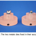 |
Figure 1: The two metals dies fixed in their acrylic bases
|
Sample grouping
Based on the technique of impression taking, sample grouping was as follows (eight samples for each group): Group I: Conventional impression using two-step putty/wash impression technique without spacer (the before-preparation putty/wash technique). Group II: Conventional impression using two-step putty/wash impression technique with spacer. Group III: Conventional impression using one-step single viscosity (monophase) impression technique. Group IV: Conventional impression using one-step dual viscosity impression technique. Group V: Digital intra-oral impression using CEREC Omnicam intra-oral scanner.
Conventional Impression Techniques
All the conventional impressions were made in a customarily made acrylic tray that was adaptable to the bases of both metal dies (the before- and after-preparation metal dies). Vinyl polysiloxane impression material (Express XT, 3M ESPE, Germany) was used in different viscosities for both one-step and two-step conventional impression techniques. Pentamix 3 automatic mixing unit was used for mixing and dispensing the penta putty and heavy body impression materials automatically, while a garant dispenser was used for auto-mixing and dispensing the light and regular body impression materials.
Group I
In the first step of this technique, a preliminary impression was taken for the master metal die of the unprepared tooth with the putty-bodied impression material (Express XT penta putty, 3M ESPE, Germany). Four relieving channels were then cut in the inner surface of the preliminary putty impression using putty-cut cutting instrument (Zhermack, Italy) to provide an escape way for the excess of the light body (wash) material used in the second step of this technique in which, a standardized amount of light body impression material was injected around the metal die of the prepared tooth and into the preliminary putty impression using impression syringe. The tray was then seated on the master metal die of the prepared tooth using a modified dental surveyor. After the setting time of the impression material, the tray with the set light body material was removed from the metal die.
Group II
In the first step of this technique, the tray was loaded with the putty-bodied impression material, and then 1 mm thickness polyethylene separation wafer (GC corp., USA) was used as a spacer and was placed over the loaded custom tray to provide a space for the light body impression material in the second step. The loaded tray with the spacer was then seated on the metal die of the prepared tooth. After the setting time of the putty impression material, the tray with the set impression material was then pulled away from the metal die and the spacer was removed. In the second step of this technique a standardized amount of the light body impression material was used as a wash material as for Group I.
Group III
In this technique, regular body (medium body) impression material was used as a tray and as a syringe material simultaneously.
Group IV
In this technique, heavy body and light body impression materials were used simultaneously to take the impression. Each conventional impression technique was repeated eight times.
Each impression was inspected under a magnifying lens before being poured. All impressions were poured with type IV extra-hard die stone (Elite® rock, Zhermack, Italy) with a water/powder ratio of 20ml/100g as recommended by the manufacturer. The poured dies were separated from the impressions after 45 minutes according to the manufacturer’s instructions and were inspected under a magnifying lens for any defect at the area of the preparation. After separation of the stone dies, the set impressions were removed from the tray and three impressions out of eight were selected randomly from each group.
Macroscopical examination of the selected impressions was done using Nikon D7100 professional camera with macro-lens 150 mm. Each impression was sectioned longitudinally in a bucco-palatal direction with a sharp blade and photographs were then taken for the sectioned impressions. Macroscopical examination was done to show the uniformity of the wash material and its relation to the tray material (Figure 2).
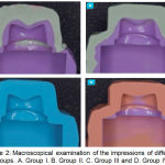 |
Figure 2: Macroscopical examination of the impressions of different groups. A. Group I. B. Group II. C. Group III and D. Group IV.
|
Digital Impression-Group V
The master metal die of the prepared tooth was removed from its acrylic base and seated in a full-arch dental simulation unit to simulate the actual clinical treatment situation. Eight digital impressions were then taken for the master die using CEREC Omnicam digital intra-oral scanner (Sirona Dental Systems, Bensheim, Germany). The scanning procedure (data acquisition) was done following the manufacturer’s instructions started occlusaly, buccaly, palatally then interproximally. The resulting 3-D virtual image for the scanned metal die was saved as STL (standard transformation language) file format.
Digital workflow and crown fabrication
The laboratory procedure for crown fabrication for the conventional impression groups was done using Sirona inLab CAD SW 15.1. Crown fabrication was done following the standard protocol of CAD/CAM crown fabrication by Sirona starting with the “SCAN PHASE” using inEos X5 extra-oral scanner. The resulting digital 3-D virtual models obtained from intra-oral and extra-oral digital scanning were then subjected to the same steps of digital workflow for crown fabrication as follows: “MODEL PHASE”, where the position of the tooth in the dental arch, the jaw line, the preparation margin and the tooth insertion axis were all determined. “DESIGN PHASE”, where the restoration parameters (80 μm cement space starting 1mm above the margin), the morphology and the position of the restoration were determined. For standardization purposes, the monolithic zirconia crowns of all groups were milled by the same milling device (MC X5, Sirona, Germany). After completion of the milling process, all crowns were densely sintered using inFire HTC speed furnace (Sirona, Germany) with pre-programmed settings according to the manufacturer’s instructions.
Fit recording by Silicone Replica Technique
A specially designed split mold for silicone replica technique was fabricated for this study from laboratory silicone duplicating material. This mold consisted of two halves joined together with two metal rods. The intaglio of each crown was filled with a standardized amount of low viscosity silicone impression material (Express XT, Light body, 3M ESPE, Germany) (violet color). Each crown was then seated slowly on the master metal die of the prepared tooth with a constant defined load of 5 Kg in an occlusal direction using a modified dental surveyor to simulate the clinical crown cementation procedure.20 After the setting time of the light body impression material, the load was removed away and the two halves of the split mold were placed over the cemented crown and assembled together via the two metal rods to hold the crown inside. After removal of the crown from the master metal die, the thin layer of the light impression material adhered to the intaglio surface of the crown due to its relatively higher roughness as compared to the smooth polished surface of the metal die.21,17 In order to stabilize this thin silicone layer during sectioning procedure (carried out later on) and to avoid its damage, a heavy body silicone impression material of contrasting color (orange-colored) (ExpressTM XT pentaTM H, 3M ESPE, Germany) was poured inside the crown until the whole split mold was filled to form one piece with the thin layer of the light body impression material to create the silicone replica. Each silicone replica was then sectioned in a bucco-palatal direction and then in a mesio-distal direction using a cutting blade in a specially designed sectioning base. The thickness of the light body silicone impression material representing the marginal and internal gaps was measured at 21 predetermined points using a digital microscope at a magnification of 230x. These measuring points represent four different areas: margin, chamfer, axial, and occlusal areas (Figure 3).
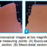 |
Figure 3: Microscopical images at low magnification showing the measuring points: (A) Bucco-palatal section. (B) Mesio-distal section.
|
For each specimen, the internal gap was measured by calculating the mean value of the chamfer, axial and occlusal area gaps. Image analyzing software (Image J, Version 1.51) which was used for the measurement of the gap width at these predetermined points. All measurements were performed by the same operator three times to avoid errors when choosing starting and ending points of the measurements, as recommended by Holmes et al.22
Results and Discussion
The descriptive statistics showed that for all groups, the highest mean value of the gap was recorded at the occlusal area, while the lowest mean value of the gap was recorded at the marginal area. The descriptive statistics also showed that in general, Group V recorded the least marginal and internal gaps while Group IV showed the highest marginal and internal gaps as compared with the other groups (Table 1).
Comparison of the marginal and internal gaps among the different groups using one-way ANOVA test revealed a statistically high significant difference among groups (p<0.01) (Table 2). Further comparisons of the marginal and internal gaps among groups were done using LSD test revealed that there were statistical differences in the marginal and internal gaps (either significant or highly significant) between the different groups, except between Group III and Group IV where there was no statistically significant difference (p>0.05) (Table 3).
Comparison between marginal and internal gaps of each group using independent t-test showed that there was a statistically highly significant difference between marginal and internal gaps of each group (p<0.01) (Table 4).
Correlation test between marginal and internal gaps of each group was done using Pearson’s correlation showed that there was a positive correlation between marginal and internal gaps in all groups with varying degree of strength and statistical significance (Table 5).
Table 1: Descriptive statistics of the gap at the different areas of the five different groups measured in μm
| Groups | Areas | No. | Mean | ±SD | Min | Max |
| Group I | Marginal | 8 | 60.299 | 6.281 | 51.538 | 68.030 |
| Chamfer | 8 | 149.724 | 7.574 | 140.184 | 162.861 | |
| Axial | 8 | 80.424 | 5.567 | 67.643 | 85.166 | |
| Occlusal | 8 | 171.100 | 9.963 | 161.516 | 186.006 | |
| Internal | 8 | 133.749 | 3.975 | 128.386 | 139.763 | |
| Group II | Marginal | 8 | 68.803 | 6.178 | 57.723 | 75.245 |
| Chamfer | 8 | 157.709 | 6.81 | 147.42 | 165.953 | |
| Axial | 8 | 84.714 | 3.925 | 80.428 | 91.361 | |
| Occlusal | 8 | 176.894 | 3.552 | 170.845 | 181.924 | |
| Internal | 8 | 139.772 | 3.143 | 135.035 | 143.813 | |
| Group III | Marginal | 8 | 81.43 | 8.711 | 67 | 89.676 |
| Chamfer | 8 | 174.457 | 7.114 | 166.984 | 188.63 | |
| Axial | 8 | 94.231 | 6.782 | 85.166 | 103.752 | |
| Occlusal | 8 | 184.693 | 7.078 | 176.676 | 193.586 | |
| Internal | 8 | 151.126 | 5.228 | 143.914 | 161.989 | |
| Group IV | Marginal | 8 | 86.588 | 3.308 | 80.4 | 91.738 |
| Chamfer | 8 | 166.21 | 7.922 | 153.584 | 174.199 | |
| Axial | 8 | 111.45 | 4.111 | 105.209 | 116.507 | |
| Occlusal | 8 | 177.987 | 9.149 | 167.929 | 194.169 | |
| Internal | 8 | 151.882 | 5.354 | 145.739 | 160.41 | |
| Group V | Marginal | 8 | 53.533 | 6.44 | 42.261 | 59.784 |
| Chamfer | 8 | 133.226 | 21.675 | 103.076 | 153.584 | |
| Axial | 8 | 95.096 | 8.359 | 80.428 | 108.125 | |
| Occlusal | 8 | 156.996 | 8.912 | 141.107 | 166.18 | |
| Internal | 8 | 128.439 | 6.425 | 120.497 | 135.813 |
Table 2: One-way ANOVA test for comparison of the marginal and internal gaps among the different groups
| Areas | ANOVA | Sum of Squares | df | Mean Square | F | Sig. |
| Marginal | Between Groups | 6179.452 | 4 | 1544.863 | 37.507 | .000(HS) |
| Within Groups | 1441.619 | 35 | 41.189 | |||
| Total | 7621.071 | 39 | ||||
| Internal | Between Groups | 3462.697 | 4 | 865.674 | 35.196 | .000(HS) |
| Within Groups | 860.842 | 35 | 24.595 | |||
| Total | 4323.539 | 39 |
Table 3: LSD test for comparison of the marginal and internal gaps among groups
| Area | Group | Mean Difference | Standard Error | Sig. | |
| Marginal | Group I | Group II | -8.50388* | 3.20894 | .012(S) |
| Group III | -21.13087* | 3.20894 | .000(HS) | ||
| Group IV | -26.28887* | 3.20894 | .000(HS) | ||
| Group V | 6.76638* | 3.20894 | .042(S) | ||
| Group II | Group III | -12.62700* | 3.20894 | .000(HS) | |
| Group IV | -17.78500* | 3.20894 | .000(HS) | ||
| Group V | 15.27025* | 3.20894 | .000(HS) | ||
| Group III | Group IV | -5.15800 | 3.20894 | .117(NS) | |
| Group V | 27.89725* | 3.20894 | .000(HS) | ||
| Group IV | Group V | 33.05525* | 3.20894 | .000(HS) | |
| Internal | Group I | Group II | -6.02325* | 2.47969 | .020(S) |
| Group III | -17.37762* | 2.47969 | .000(HS) | ||
| Group IV | -18.13350* | 2.47969 | .000(HS) | ||
| Group V | 5.30988* | 2.47969 | .039(S) | ||
| Group II | Group III | -11.35438* | 2.47969 | .000(HS) | |
| Group IV | -12.11025* | 2.47969 | .000(HS) | ||
| Group V | 11.33313* | 2.47969 | .000(HS) | ||
| Group III | Group IV | -.75587 | 2.47969 | .762(NS) | |
| Group V | 22.68750* | 2.47969 | .000(HS) | ||
| Group IV | Group V | 23.44338* | 2.47969 | .000(HS) | |
Table 4: t-test for comparison between the marginal gap and the internal gap for each group
| Group | Gap | Mean | ±SD | t-test | p-value | Sig. |
| Group I | Marginal | 60.299 | 6.281 | 27.945 | .000 | HS |
| Internal | 133.749 | 3.975 | ||||
| Group II | Marginal | 68.803 | 6.178 | 28.958 | .000 | HS |
| Internal | 139.772 | 3.143 | ||||
| Group III | Marginal | 81.430 | 8.711 | 19.403 | .000 | HS |
| Internal | 151.126 | 5.228 | ||||
| Group IV | Marginal | 86.588 | 3.308 | 29.341 | .000 | HS |
| Internal | 151.882 | 5.354 | ||||
| Group V | Marginal | 53.533 | 6.440 | 23.289 | .000 | HS |
| Internal | 128.439 | 6.425 |
Table 5: Correlation test between marginal and internal gaps of each group.
| Group | Gap | r | P-value | Sig. |
| Group I | Marginal | 0.121 | 0.775 | P>0.05
(NS) |
| Internal | ||||
| Group II | Marginal | 0.929 | 0.001 | P˂0.01
(HS) |
| Internal | ||||
| Group III | Marginal | 0.598 | 0.117 | p>0.05
(NS) |
| Internal | ||||
| Group IV | Marginal | 0.301 | 0.468 | p>0.05
(NS) |
| Internal | ||||
| Group V | Marginal | 0.672 | 0.068 | p>0.05
(NS) |
| Internal |
Ideally, the cement space should be uniform to facilitate seating without compromising retention and resistance form.23 However, even though a uniform cement space was set 80 μm in this study, starting 1 mm above the margin according to the manufacturer, the resulting cement space was not as precise and uniform as the set parameter, the resulting gap was larger than the set cement space at all areas of measurements for all groups. This could be generally related to one, or a combination, of the followings:
The cementation procedure which results in an increase in the marginal and internal gaps as reported by Okutan et al.24 and Ural et al.25 The replica technique used in this study is a simulation of the clinical cementation procedure whereby light body impression material acts as cement analog.18,26
The limitation of the digital workflow that could be related to the quality of acquisition and processing of the digital data, the relief of retentive areas and the limited ability of the milling instruments to reproduce fine details.27,28
The anisotropic shrinkage of the partially-sintered zirconia restorations that occurred after sintering procedure.29 Although a compensatory software design was used to guarantee an accurate fit, it is not sure that the shrinkage can be completely controlled.30
The calculation of the CAD/CAM software may not be as precise as it should be. Therefore, it has to be considered that a tendency for the greater gaps than the expected value could be found.31
The results of this study showed that the marginal and internal gaps of monolithic zirconia crowns produced from both two-step putty/wash impression techniques (Groups I and II) were significantly less than the marginal and internal gaps of crowns produced from both one-step impression techniques (Groups III and IV). The superiority of the two-step impression technique over the one-step impression technique could be attributed to the followings:
In the two-step technique, the fine details are registered by the light body material at the second step of the technique, which has better flow characteristics owing to its lower viscosity due to decreased filler contents,32,33 while in the one-step impression technique, the tray material tends to push the syringe material off the prepared tooth, so it is impossible to control which material records the details of the margin of the preparation. Thus, critical areas such as the finish line might be captured by the tray material (whether heavy body or regular body) rather than the syringe material, which cannot record the fine details to a satisfactory level because of its higher volume of filler content that causes less elasticity and fluidity and results in lower accuracy,34,35,36 as seen in the macroscopical examination of the of the retrieved impressions in this study.
In the one-step impression technique, when mixing the tray material at the same time as the syringe material, the setting distortion of the tray material is included in the overall distortion of the impression.37 In other words, in the one-step technique, the volume of the material subjected to distortion is increased as compared with the two-step technique in which the distortion of the tray material occurs during the first step of the technique and the final distortion is limited to the thin film of the light body material.
The above result is in agreement with Nissan et al.38 who found that the marginal fit of the milled cast crowns fabricated from different impression techniques was better with the two-step putty/wash impression technique than the one-step impression technique. This finding is also in agreement with Caputi and Varvara6 and Levartovsky et al.35 who all showed that the two-step technique is more accurate than the one-step technique in terms of the dimensional accuracy of the resultant stone casts. However, the above result disagrees with Hung et al39 and Mishra and Chowdhary40 who all found that the two-step putty/wash impression technique was as accurate as the one-step impression technique.
It is well-established that the key factor influencing the accuracy of the impression technique is the controlled and uniform bulk of the light body (wash) material. It has been found that the optimum bulk of the wash material for vinyl polysiloxane is 1-2 mm.41 When comparing between both subtypes of the two-step putty/wash impression techniques, the result of this study showed that crowns fabricated from (Group I) showed better marginal and internal fitness than crowns fabricated from (Group II) with statistically significant difference. This could be explained according to the macroscopical examination of the impressions retrieved from the different impression techniques which showed that, the two-step putty/wash technique (the before-preparation technique) was the only technique that was able to provide a controlled and uniform thickness of the light body material owing to the controlled tooth preparation of 1.5 mm.
The controlled wash space was provided by taking the preliminary impression before tooth preparation with the putty material then relining the impression with the wash material after tooth preparation. On the other hand, the use of polyethylene spacer in the two-step putty/wash technique (Group II) was able to provide a space for the wash material, but this space was not uniform all around the tooth preparation due to the flexible and compressible nature of this spacer that tends to fold and accumulate at certain areas, and thus may create slight dimensional inaccuracy due to the non-uniform wash material.42
Another factor that might contribute to the better fitness of crowns of Group I over crowns of Group II was the use of relieving channels in the preliminary putty impression which acted as a vent for the escape of the excess of the wash material during the second step of this technique, thus preventing the compression of the light body impression material by the heavier consistency putty material. The above finding is in agreement with Nissan et al.7 Chugh et al,43 Nissan et al.38 and Shiozawa et al.44 who all found that a uniform and controlled wash space in the two-step putty/wash impression technique produced smaller discrepancies than the polyethylene putty/wash impression techniques. However, the above finding disagrees with Sayed et al.42 who found that the dimensional accuracy of stone casts produced from two-step putty/wash impression technique with a spacer was better than the ones produced from two-step putty/wash (the before-preparation) impression technique. Such disagreement could be due to not using relieving channels in the preliminary putty impression and thus, the wash material seems to be trapped inside the set tray material leading to inaccuracy. If no relief is performed on the preliminary impression, there is no space to allow the wash material to flow which complicates the reset of the primary impression.
On the other hand, the statistically non-significant difference between both one-step impression techniques (Group III and Group IV) could be due to that both techniques had the same basic steps, in which the tray material and the syringe material are mixed and loaded simultaneously, so the tray material and the syringe material join, bond and set together. However, despite this statistically non-significant difference, the overall mean value of the marginal gap of the one-step single viscosity (monophase) impression technique (Group III) was smaller than that of the one-step dual viscosity impression technique (Group IV). This could be due to the difference in viscosity of the tray material in both techniques: in the dual viscosity technique, the heavy body might force the light body material away and thus, the critical area of the finishing line might be recorded with the heavy body material. On the contrary, the same scenario might not occur with the single viscosity technique due to the lower viscosity of the tray material, and even if the same scenario occurred, the critical area of the finishing line would be registered with the regular body material, which has better flow ability and detail reproduction.
The results of this study revealed that the intra-oral digital impression (Group V) showed the least marginal and internal gaps with statistically significant and highly significant differences when compared with all other conventional impression groups (Groups I-IV). The better overall fit of the intra-oral digital group could be attributed to the errors that might occur either during the steps of conventional impression making and/or during the extra-oral scanning of the stone models. In this study, in spite of following the manufacturer’s instructions and a standard protocol for all steps of conventional impression making, still sources of inaccuracy are inevitable. First of all, no material has 100% elastic recovery.45 In addition, in the conventional impression workflow, a stone model is created which is the basis for the construction of the crown, while in the digital workflow the crown is designed directly from the intra-oral scan without creating an intermediate model.21
Moreover, using direct intra-oral scanner eliminates most errors associated with conventional impression taking including dimensional changes (expansion/contraction) of the impression material and gypsum used to fabricate master model.46 It has been reported that type IV dental cast had a linear expansion between 0.06% and 0.5%.47 On the other hand, deformation of the impression while removing from the prepared tooth might be another possible source for such inaccuracy.48
Another contributing factor that might explain the better marginal and internal fitness of crowns fabricated from the direct intra-oral scanning as opposed to conventional impression is the accuracy or the resolution of the intra-oral scanner as compared with the extra-oral scanner used to scan the stone models in the conventional impression group. CEREC Omnicam intra-oral scanner used in this study provides a color streaming technology which allows a continuous video capture with anti-shake property and emits white light with shorter wavelength than the blue light emitted by the inLab inEos X5 extra-oral scanner used to scan the stone model, which is less susceptible to bending, scattering and transmission by the scanned object thus, it is more accurate.49,50 The above finding is in agreement with Syrek et al.21 e Silva et al.51 Khdaier,52 Pradies et al53 and Kocaağaoğlu et al.54 who all found that intra-oral digital impression, regardless of the type of the scanner used, provided better marginal and internal fitness than conventional impressions regardless of the diversity in the conventional impression technique. However, the results of this study disagree with Flügge et al.55 who concluded that scanning with intra-oral digital scanner is less accurate than scanning with model scanner, suggesting that the intra-oral condition such as the presence of saliva and limited spacing contribute to the inaccuracy of the scan.
In this study, crowns of all groups showed better marginal fitness than internal fitness which could be explained by the followings:
The cement space started 1 mm above the margin according to the design software as previously mentioned.
Two concomitant phenomena called “overshoot” and “rounded edges” which occur during the scanning of angled regions due to the limitation in the scanner resolution could be responsible for the wider internal gaps. Optical systems have the limitation of finite resolution when scanning angled regions as in scanning of the axio-occlusal transitional area and the central area of the occlusal surface. This will produce virtual peaks near the edges of three-dimensional structures when captured by digital scanner, a phenomenon called “overshoot” resulting in edges that are slightly rounded, a phenomenon called “round edges” which may cause distortion of the prepared tooth design in angle regions.56,57,58
Limitation in the CAM process: when concerning the CAM process, the diameter and shape of the milling instrument can limit the machining of internal contours. If the cutting tool is larger in diameter than some parts of the tooth preparation, the system will face a problem of cutting or not cutting the parts, which consequently results in decreased internal fit precision and low retention of the restoration.57,26
The above result is in agreement with Reich et al.57, Curtis et al 59 and Yildiz et al.60 who all found that the fitness of CAD/CAM crowns was less accurate in the internal region than in the marginal region.
Correlation test between marginal and internal gaps for all groups showed a positive relation between marginal and internal areas with varying degree of strength (weak, intermediate or strong). This means that, in general, when the marginal gap increased, the internal gap increased. This may be attributed to the fact that in each group, all areas of the crown (marginal, chamfer, axial and occlusal areas) were milled with the same milling unit. This may permit constant changes in the dimensions of the final restoration. The above result is in agreement with the results of a study done by Ali and Sabea61 who found a positive correlation between marginal and internal gaps of three CAD-CAM all-ceramic crowns materials: Zolid, Zircon and Empress. Moreover, Al-Adel and Majeed62 also found a positive correlation between marginal and internal gaps of full-contour CAD/CAM crowns fabricated from zirconia, lithium disilicate, zirconia-reinforced lithium silicate and hybrid dental ceramic. From a clinical point of view, this may give an indication that any crown restoration with poor marginal adaptation will mostly have poor internal adaptation.
There is a controversy in the literature regarding the clinically acceptable ranges for the marginal gap. Many authors indicated that a marginal gap of ≤120 μm is considered clinically acceptable.63,64,65 Furthermore, for CAD/CAM-fabricated ceramic crowns, the clinically acceptable marginal gap discrepancies has been reported to range between 17 and 118 μm.66,67,68 Accordingly, the marginal gap of all groups in this study whether conventional impression groups or digital one, fall within the clinically acceptable range.
For the internal gap, the clinically acceptable range differs from one article to another yet there is no standard protocol to assess the adaptation of dental restorations. This lack of standardization may lead to misinterpretation and limits the comparisons between results from different studies. Therefore, it is important to understand the limitations of the existing techniques and the type of data that they can provide (i.e. internal gap, axial gap, occlusal gap, etc.).69 Another important factor that might hinder comparisons among studies is the cement space previously predetermined by the software of the CAD/CAM system. This factor differs from one study to another and ranges from (0-200 μm).70,71,61 It had been found that the internal gap of single zirconia restorations were in the range of 41-192 μm.72,73 Accordingly, all groups in this study fall within the above range.
It is worth to mention that despite the presence of statistical differences among the different groups in this study, the mean values of the marginal and internal gaps of all groups are all within the clinically acceptable limits. This could be attributed to two main reasons: Firstly, the use of vinyl polysiloxane impression material with reported high accuracy, elastic recovery and dimensional stability. Secondly, the development that occurred in the CAD/CAM technology including the scanning resolution, designing software and the milling units including the use of burs with smaller sizes.
Conclusions
Within the limitations of this in vitro study, the following conclusions could be drawn:
The impression technique had a significant effect on the marginal and internal fitness of monolithic CAD/CAM fabricated zirconia crowns. Monolithic zirconia crowns fabricated using digital intra-oral impression showed better marginal and internal fitness than crowns fabricated using conventional impression techniques.
Regarding the different conventional impression techniques, the before-preparation two-step putty/wash impression technique without spacer showed the least marginal and internal gaps followed by the two-step putty/wash impression technique with spacer, while both one-step impression techniques (monophase and dual viscosity) showed greater marginal and internal gaps with statistically non-significant difference between them.
For all groups, the marginal gap was less than the internal gap with a positive correlation between them.
The marginal and internal gaps of all groups were within the clinically acceptable limits. This leads to the assumption that regardless of the impression technique used, meticulous attention to the basic concept of each impression technique along with thorough understanding of the physical properties of each impression material are prerequisites to obtain an acceptable impression.
Refrences
- Renne W, McGill S.T, Forshee K, et al. Predicting marginal fit of CAD/CAM crowns based on the presence or absence of common preparation errors. J Prosthet. 2012;108(5):310-315.
CrossRef - Euán R, Figueras-Álvarez O, Cabratosa-Termes J, et al. Marginal adaptation of zirconium dioxide copings: influence of the CAD/CAM system and the finish line design. J Prosthet Dent. 2014;112(2):155-162.
CrossRef - Souza R.O, Özcan M, Pavanelli C.A, et al. Marginal and internal discrepancies related to margin design of ceramic crowns fabricated by a CAD/CAM system. J Prosthodont. 2012;21(2):94-100.
CrossRef - Persson A.S, Andersson M, Odén A, et al. Computer aided analysis of digitized dental stone replicas by dental CAD/CAM technology. J Den Mater. 2008;24(8):1123-1130.
CrossRef - Cho S.H, Schaefer O, Thompson G.A, et al. Comparison of accuracy and reproducibility of casts made by digital and conventional methods. J Prosthet Dent. 2015;113(4):310-315.
CrossRef - Caputi S, Varvara G. Dimensional accuracy of resultant casts made by a monophase, one-step and two-step, and a novel two-step putty/light-body impression technique: an in vitro study. J Prosthet Dent. 2008; 99(4):274-281.
CrossRef - Nissan J, Laufer B.Z, Brosh T, et al. Accuracy of three polyvinyl siloxane putty-wash impression techniques. J Prosthet Dent. 2000;83(2):161-165.
CrossRef - Sun M. A Laboratory Evaluation of Detail Reproduction, Contact Angle, and Tear Strength of Three Elastomeric Impression Materials. A master thesis. Department of restorative dentistry, Indiana University. 2011.
- Rubel B.S. Impression materials: a comparative review of impression materials most commonly used in restorative dentistry. J Dent Clin North Am. 2007;51(3):629-642.
CrossRef - Vennerstrom M, Fakhary M, Von Steyern P.V. The fit of crowns produced using digital impression systems. Swed Dent J. 2014;38(3):101-110.
- Tsirogiannis P, Reissmann D.R, Heydecke G. Evaluation of the marginal fit of single-unit, complete-coverage ceramic restorations fabricated after digital and conventional impressions: A systematic review and meta-analysis. J Prosthet Dent. 2016;116(3):328-335.
CrossRef - Christensen G.J. Impressions are changing: deciding on conventional, digital or digital plus in-office milling. J. Am Dent Assoc. 2009;140(10):1301–1304.
CrossRef - Peddroche L.O, Bernardes S.R, Leao M.P, et al. Marginal and internal fit of zirconia copings obtained using different digital scanning methods. Braz oral res. 2016;30(1):113.
CrossRef - Preis V, Behr M, Kolbeck C, et al. Wear performance of substructure ceramics and veneering porcelains. J Dent Mater. 2011;27(8):796-804.
CrossRef - Özkurt-Kayahan Z. Monolithic zirconia: A review of the literature. Biomed Res J. 2016;27(4):1427-1436.
- Saraswathi D.D, Leneena G, Babu M.R, et al. Comparative Evaluation of Marginal Vertical Discrepancies of Full Zirconia Crowns, Layered Zirconia Crowns, and Metal Ceramic Crowns: An In Vitro Study. J Int Oral Health. 2016;8(2):208-213.
- Trifkovic B, Budak I, Todorovic A, Hodolic et al. Application of replica technique and SEM in accuracy measurement of ceramic crowns. J Measurement Science Review. 2012;12(3):90-97.
CrossRef - Rahme H.Y, Tehini G.E, Adib S.M, et al. In vitro evaluation of the “replica technique” in the measurement of the fit of Procera crowns. J contemp Dent pract. 2008;9(2):25-32.
- Kim K.B, Kim W.C, Kim H.Y, et al. An evaluation of marginal fit of three-unit fixed dental prostheses fabricated by direct metal laser sintering system. J Dent Mater. 2013;29(7):91-96.
CrossRef - Wang C.J, Millstein P.L, Nathanson D. Effects of cement, cement space, marginal design, seating aid materials, and seating force on crown cementation. J Prosthet Dent. 1992;67(6):786-790.
CrossRef - Syrek A, Reich G, Ranftl D, et al. Clinical evaluation of all-ceramic crowns fabricated from intraoral digital impressions based on the principle of active wavefront sampling. J Dent. 2010;38(7):553-559.
CrossRef - Holmes J.R, Bayne S.C, Holland G.A, et al. Considerations in measurement of marginal fit. J. Prosthet Dent. 1989;62(4):405-408.
CrossRef - Paula D, Silveira A.C, Chaves S.B, Hilgert L.A, et al. Marginal and internal fit of CAD-CAM-fabricated composite resin and ceramic crowns scanned by 2 intraoral cameras. J Prosthet Dent. 2016;117(3):331-452.
- Okutan M, Heydecke G, Butz F, et al. Fracture load and marginal fit of shrinkage‐free ZrSiO4 all‐ceramic crowns after chewing simulation. J oral rehabil. 2006;33(11):827-832.
CrossRef - Ural Ç, Burgaz Y, Saraç D. In vitro evaluation of marginal adaptation in five ceramic restoration fabricating techniques. J Quintessence Int. 2010;41(7):585-590.
- Reich S, Uhlen S, Gozdowski S, et al. Measurement of cement thickness under lithium disilicate crowns using an impression material technique. J Clin oral investig. 2011;15(4):521-526.
CrossRef - Luthardt R, Weber A, Rudolph H, et al. Design and production of dental prosthetic restorations: basic research on dental CAD/CAM technology. Int J Comput Dent. 2002;5(2-3):165-176
- Tinschert J, Natt G, Hassenpflug S, et al. Status of current CAD/CAM technology in dental medicine. Int J Comput Dent. 2004;7(1):25-45.
- Kunii J, Hotta Y, Tamaki Y, et al. Effect of sintering on the marginal and internal fit of CAD/CAM-fabricated zirconia frameworks. J Dent Mater. 2007;26(6):820-826
CrossRef - Bona D.A. Bonding to ceramics: scientific evidences for clinical dentistry. Artes Médicas. 2009;20:252.
- Anunmana C, Charoenchitt M, Asvanund C. Gap comparison between single crown and three-unit bridge zirconia substructures. J Adv Prosthodont. 2014;6(4):253-258.
CrossRef - Boghosian A, Lautenschlager E.P. Tear strength of 10 low-viscosity elastomeric impression materials. J. Dent Res. 2003;82:137.
- LOWE R.A. Mastering the art of impression making. J Inside Dentistry. 2006;2(1):38-39.
- Chen S.Y, Liang W.M, Chen F.N. Factors affecting the accuracy of elastometric impression materials. J Dent. 2004;32(8):603-609.
CrossRef - Levartovsky S, Zalis M, Pilo R, et al. The Effect of One‐Step vs. Two‐Step Impression Techniques on Long‐Term Accuracy and Dimensional Stability when the Finish Line is within the Gingival Sulcular Area. J Prosthodont. 2014;23(2):124-33.
CrossRef - Basapogu S, Pilla A, Pathipaka S. Dimensional Accuracy of Hydrophilic and Hydrophobic VPS Impression Materials Using Different Impression Techniques-An Invitro Study. J Clin Diag Res. JCDR. 2016;10(2):56-59.
- Chee W.W, Donovan T.E. Polyvinyl siloxane impression materials: a review of properties and techniques. J Prosthet Dent. 1992;68(5):728-732.
CrossRef - Nissan J, Rosner O, Amin Bukhari M, et al. Effect of various putty-wash impression techniques on marginal fit of cast crowns. Int J Periodontics Restorative Dent. 2013;33(1):37-42.
CrossRef - Hung S.H, Purk J.H, Tira D.E, et al. Accuracy of one-step versus two-step putty wash addition silicone impression technique. J Prosthet Dent. 1992;67(5):583-589.
CrossRef - Mishra S, Chowdhary R. Linear dimensional accuracy of a polyvinyl siloxane of varying viscosities using different impression techniques. J Investig Clin Dent. 2010;1(1):37-46.
CrossRef - Nissan J, Gross M, Shifman A, et al. Effect of wash bulk on the accuracy of polyvinyl siloxane putty‐wash impressions. J Oral Rehabil. 2002;29(4):357-361.
CrossRef - Sayed N.M, Aly N.H, Rayyan M.M. The effect of different double-step impression techniques on accuracy of stone dies. Egypt Dent J. 2015; 61(1):641-650.
- Chugh A, Arora A, Singh V.P. Accuracy of different putty-wash impression techniques with various spacer thickness. Int J Clin Pediatr Dent. 2012;5(1):33-38.
CrossRef - Shiozawa M, Takahashi H, Finger W.J, et al. Effects of the space for wash materials on sulcus depth reproduction with addition-curing silicone using two-step putty-wash technique. J Dent Mater. 2013; 32(1):150-155.
CrossRef - Klooster J, Logan G.I, Tjan A.H. Effects of strain rate on the behavior of elastomeric impression. J prosthet Dent. 1991;66(3):292-298.
CrossRef - ZARAUZ C, VALVERDE A, MARTINEZ-RUS F, et al. Clinical evaluation comparing the fit of all-ceramic crowns obtained from silicone and digital intraoral impressions. J Clin oral Investig. 2016;20(4):799-806.
CrossRef - Kenyon B.J, Hagge M.S, Leknius C, et al. Dimensional accuracy of 7 die materials. J Prosthodont. 2005;14(1):25-31.
CrossRef - Abdel-Azim T, Rogers K, Elathamna E, et al. Comparison of the marginal fit of lithium disilicate crowns fabricated with CAD/CAM technology by using conventional impressions and two intraoral digital scanners. J Prosthet Dent. 2015;114(4):554-559.
CrossRef - Baheti M.J, Soni U.N, Gharat N.V, et al. Intra-oral Scanners: A new eye in dentistry. Austin J Orthopade Rheumatol. 2015;2(3):1021.
- Salem N.M, Kader S.H, Al Abbassy F, et al. Evaluation of fit accuracy of computer-aided design/computer-aided manufacturing crowns fabricated by three different digital impression techniques using cone-beam computerized tomography. Eur J Prosthodont. 2016;4(2):32-36.
CrossRef - Esilva J.S, Erdelt K, Edelhoff D, et al. Marginal and internal fit of four-unit zirconia fixed dental prostheses based on digital and conventional impression techniques. J Clin oral Investig. 2014;18(2):515-523.
CrossRef - Khadaier R.M. Marginal fitness of CAD/CAM all ceramic crowns constructed by direct and indirect digital impression techniques(An In vitro-Study). A master thesis university of Baghdad. 2015.
- Pradíes G, Zarauz C, Valverde A, et al. Clinical evaluation comparing the fit of all-ceramic crowns obtained from silicone and digital intraoral impressions based on wavefront sampling technology. J Dent. 2015;43(2):201-208.
CrossRef - Kocaağaoğlu H, Kılınç H.I, Albayrak H. Effect of digital impressions and production protocols on the adaptation of zirconia copings. J Prosthet Dent. 2017;117(1):102-108.
CrossRef - Flügge T.V, Schlager S, Nelson K, et al. Precision of intraoral digital dental impressions with iTero and extraoral digitization with the iTero and a model scanner. Am J Orthodo Dentofacial Orthop. 2013;144(3):471-478.
CrossRef - Pfeiffer J. Dental CAD/CAM technologies: the optical impression (II). Int J. comput dent. 1999;2(1):65-72.
- Reich S, Wichmann M, Nkenke E, et al. Clinical fit of all‐ceramic three‐unit fixed partial dentures, generated with three different CAD/CAM systems. Eur J oral sci. 2005;113(2):174-179.
CrossRef - Abduo J, Lyons K, Swain M. Fit of zirconia fixed partial denture: a systematic review. J Oral Rehabil. 2010;37(11):866-876.
CrossRef - Curtis A.R, Wright A.J, Fleming G.J. The influence of simulated masticatory loading regimes on the bi-axial flexure strength and reliability of a Y-TZP dental ceramic. J Dent. 2006;34(5):317-325.
CrossRef - Yildiz C, Vanlioglu B.A, Evren B, et al. Marginal-internal adaptation and fracture resistance of CAD/CAM crown restorations. J Dent Mater. 2013;32(1):42-47.
CrossRef - Ali A.A.A, Sabea N.R. Comparison of marginal adaptation, internal fitness and microleakage of Zolid, Zirconia and Empress 2 all-ceramic crown materials (An in vitro study). J Must Dent. 2013;10(2):184-192.
- Al-Adel S.K, Majeed M.A. Evaluation of the marginal and internal fitness of full-contour CAD/CAM crowns made from zirconia, lithium disilicate, zirconia-reinforced lithium silicate and hybrid dental ceramic by silicone replica technique (A comparative In vitro study). J Gerc. 2016;4(1):10-20.
- May K.B, Russell M.M, Razzoog M.E, et al. Precision of fit: the Procera AllCeram crown. J. Prosthet Dent. 1998;80(4):394-404.
CrossRef - Tsitrou E.A, Northeast S.E, van Noort R. Evaluation of the marginal fit of three margin designs of resin composite crowns using CAD/CAM. J Dent. 2007;35(1):68-73.
CrossRef - Al-Zubaidi Z.A, Al-Shamma A.M. The Effect of Different Finishing Lines on the Marginal Fitness of Full Contour Zirconia and Glass Ceramic CAD/CAM Crowns (An in-vitro study). J Dent Mater Tech. 2015; 4(3):127-136.
- Balkaya M.C, Cinar A, Pamuk S. Influence of firing cycles on the margin distortion of 3 all-ceramic crown systems. J Prosthet Dent. 2005;93(4):346-355.
CrossRef - Lee K.B, Park C.W, Kim K.H, et al. Marginal and internal fit of all-ceramic crowns fabricated with two different CAD/CAM systems. J Dent Mater. 2008;27(3):422-426.
CrossRef - Ibraheem A.F, Abdulkareem A.M. Comparison of the Marginal Fitness of the Ceramic Crowns Fabricated with Different CAD/CAM Systems: An in Vitro Study. J Baghdad College Dent. 2016;28(4):28-33.
CrossRef - Colpani J.T, Borba M, Della Bona Á. Evaluation of marginal and internal fit of ceramic crown copings. J Dent Mater. 2013;29(2):174-180.
CrossRef - Iwai T, Komine F, Kobayashi K, et al. Influence of convergence angle and cement space on adaptation of zirconium dioxide ceramic copings. J Acta Odontol Scand. 2008;66(4):214-218.
CrossRef - Ardekani K.T, Ahangari A.H, Farahi L. Marginal and internal fit of CAD/CAM and slip-cast made zirconia copings. J Dent Res Dent Clin Dent prospects. 2012;6(2):42-48.
- Coli P, Karlsson S. Fit of a new pressure-sintered zirconium dioxide coping. Int J Prosthodont. 2004;17(1):59-64.
- Bindl A, Mörmann W.H. Marginal and internal fit of all‐ceramic CAD/CAM crown‐copings on chamfer preparations. J Oral Rehabil. 2005;32(6):441-447.
CrossRef

